ME 381 Project 2 Assemblies and Drawings
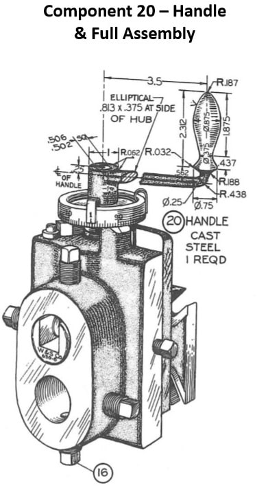
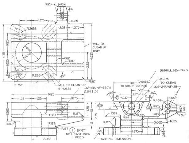
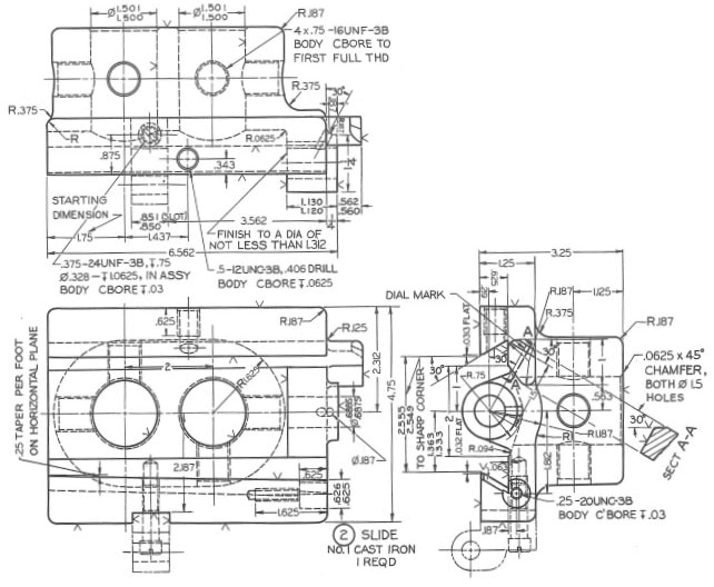
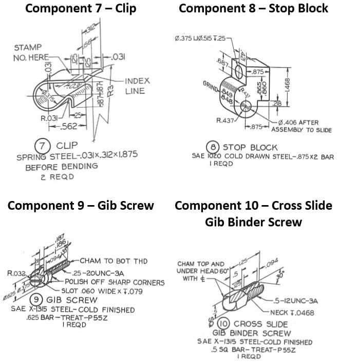
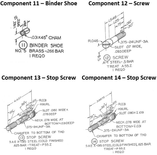
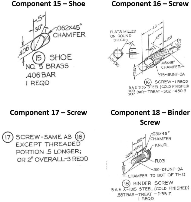
Create a model of a vertical slide tool. Assemble the components into an assembly, with separate subassemblies for the body (1) and slide (2). Create a solid part model for each of the non-standard parts using the dimensions shown in the sketches on the following pages. Dimensions are provided in inches. Use standard Creo library parts or downloaded components for commercially available standard parts (10, 12 and 19). If required, make any modifications needed to standard parts. Using good engineering judgment, estimate any dimensions not given. Create drawings for modified standard parts showing the modifications. Chamfer, fillet, or round where required for a well-designed component.
Special notes: some parts indicate use of 0.5”-12UNC threads. This thread is no-longer used. Replace with 0.5”-13 UNC threads. Also, replace any use of 0. 625”-10NS threads with 0.625”-11 UNC thread. Finally, ignore any material specifications in drawings.
Submit the following:
- One zip folder with all assembly, sub-assembly, part, and drawing files appropriately identified. Use Blackboard to submit project files. There will be a minimum of twenty-seven (40) files: two assembly files, seventeen non-standard part files, three standard part files, and a minimum of twenty drawing files. Note: Do NOT submit any part, assembly, or drawing file not included in the final assembly. Do NOT submit previous versions of files. Points will be deducted from the
“Good Engineering Practice” score for extra files.
- Hardcopies (paper copies) of all necessary drawings: assembly, subassembly, and detail component drawings. The assembly drawings must be exploded views. There will be a minimum of twenty (20) paper drawings. All drawings must be signed/dated.
Evaluation will be based on the following: Correctness (60%), Drawings (30%), and Good Engineering Practice (10%).
Required tasks:
- Two subassemblies must be created and included in the final assembly.
- Downloaded files can be used for Items 10, 12 and 19.
- All drawings must be properly formatted.
- All detail drawings must be properly dimensioned.
- Meaningful tolerances must be determined and shown for all mating and other
“significant” dimensions. (GD&T is not required.)
Bill of Materials for tool post and holder *= Standard parts
|
Item |
Description |
Qty |
Material |
|
1 |
Body |
1 |
Cast Iron |
|
2 |
Slide |
1 |
Cast Iron |
|
3 |
Dial |
1 |
Cast Iron |
|
4 |
Adjusting Screw |
1 |
303 Stainless Steel |
|
5 |
Gib |
1 |
SAE 1020 CRS |
|
6 |
Bushing |
1 |
SAE 1035 Steel |
|
7 |
Clip |
2 |
Spring Steel |
|
8 |
Stop Block |
1 |
SAE 1020 CRS |
|
9 |
Gib Screw |
1 |
SAE 1315 Cold Finished |
|
10* |
Cross Slide Gib Binder Screw |
1 |
SAE 1315 (or similar) |
|
11 |
Binder Shoe |
1 |
Brass |
|
12* |
Screw (replace with modified socket head cap screw) |
1 |
303 Stainless Steel (or similar) |
|
13 |
Stop Screw |
1 |
SAE 1315 Cold Finished |
|
14 |
Stop Screw |
1 |
SAE 1315 Cold Finished |
|
15 |
Shoe |
1 |
Brass |
|
16 |
Screw |
1 |
SAE 3135 Cold Finished |
|
17 |
Screw |
3 |
SAE 3135 Cold Finished |
|
18 |
Binder Screw |
1 |
SAE 1315 Cold Finished |
|
19* |
No. 2 Taper Pin |
1 |
Any Available |
|
20 |
Handle |
1 |
SAE 1020 CRS |
Component 1 – Body
Component 2 – Slide
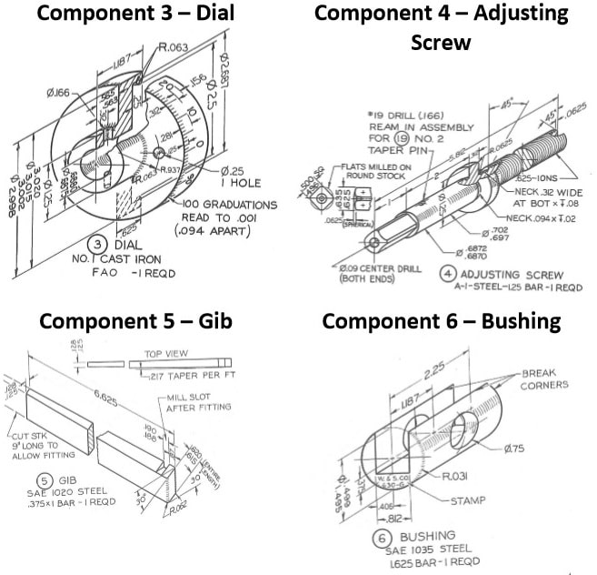
Component 19 – See Note in Component 4 Drawing
