MAE5010-B Control Engineering
Objectives:
- In Part I of this assignment you will use the Root Locus method to design a compensator for a plant to satisfy a set performance specifications. You will use Matlab to verify your calculations.
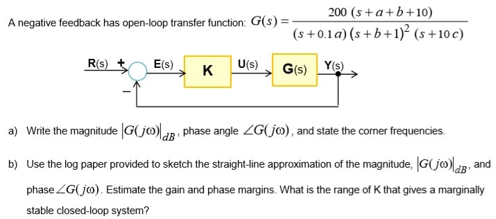
- In Part II of this assignment you will draw the straight-line approximation of the Bode plots and calculate the phase and gain margins
Submission:
Submit a typed Word report that documents your answers to each section and provides the appropriate plots and put the Matlab code you generated at the end of the report. Do not use screenshots but export your graphs using ‘copy figure’ then paste into your report.
Compensator Design via the Root Locus
The root locus plot displays the system closed-loop pole locations as a parameter (usually the controller gain) varies from zero to infinity. For a given plant, it may not be possible to achieve the desired closed-loop performance by adjusting the controller gain (proportional control). In this case, a compensator that introduces additional poles and zeros is needed to change the shape of the root locus in a desired manner.
Problem Statement:

The constants a, b, and c are the last three digits of your UoB number, for instance if your UoB number is 12610906 then select a = 9, b = 0, c = 6.
Part A: Root Locus Plot – 25%
Let C(s) = K, where K {`>`}0
1) Use Word drawing tool to sketch manually the root locus and determine:
- The number of branches, the asymptotes and their angles and intersection with the real axis. Use arrows to show direction of increasing gain on each branch of the root locus
- The breakaway point and the value of K at this point
- The range of K that yield a stable closed-loop system
Discuss how the closed-loop system behaves when the gain K is increased from zero to infinity. Explain closed-loop behaviour in terms of type of response, stability, overshoot/damping, settling time, dominant time constant, etc.
2. Write down the expression for the position constant and hence determine the theoretical value of K that gives a steady-state error of 10% to a unit step input. Is this value of K within the stability range? Is there a value of K that reduces the error to zero? Justify your answer.
Part B: Compensator Design C(s) – 45%
Use the Root Locus approach to design the simplest compensator possible that achieves the following requirements
- Zero steady-state error for a step input
- Overshoot of 20% or less is acceptable.
- 5% Settling time of 2 seconds or less if possible
Show all the intermediate steps and calculations of your design procedure and explain the reason(s) you chose the compensator. Once your compensator has been designed check with Matlab to see if all the performance specifications have been met.
If the compensated system does not meet all the requirements you will need to adjust the compensator zero(s) until the specifications are achieved. Discuss your approach. Use Matlab to check your results.
Calculate the steady-state error for a unit step input. Use Matlab to plot the closed-loop unit step response of the compensated system and compute the closed-loop poles.
Bode Plot - 30%


