ENSC 805 Project
Objectives
The project provides students the opportunity to research timing synchronization (at both the bit and frame levels) and implement these algorithms, in conjunction with a differential detector, (using Matlab) to recover the data contained in a corrupted waveform. In addition to differential detection, the project is set up in such a way that the students can experiment with ideas such as
- coherent detection via pilot symbols and channel interpolation,
- diversity and signal combining (essentially a repetition code) to improve data reliability, and
- other sophisticated detection techniques.
Expectation and Grading
It is expected that the student can successfully implement the differential detector and related timing synchronization algorithms.
Additional marks will be given if the student can successfully implement a pilot-symbol assisted detector, and/or a diversity combining receiver.
Signal model
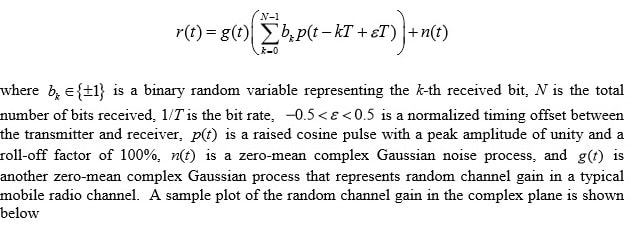
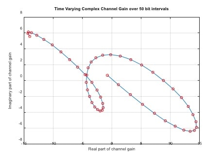
You are provided with T/2-spaced samples of the waveform


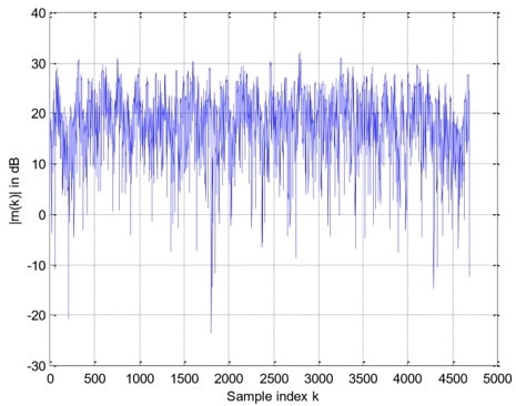
The receiver’s A/D converter samples the above signal at t = nT /2, n = 0,1,…,2N-1 and obtains the 2NT/2-spaced samples rn(0), rn(1), , rn(2N-1). A sample plot of the magnitude of rn(k) versus k is shown below. Looks messy, isn’t it? This is because of the random channel gain. Don’t worry though, if you do things right, you can recover the message embedded in this noise-like waveform.

Data Structure
The N received bits b0, b1,...bN-1 are divided into 4 groups as shown below.
|
N1 junk bits |
32 bits of preamble |
N2 data bits |
N3 junk bits |
You will be given (indirectly) the value of N2 , but you are not given the values of N1 and N3. This means you need to perform frame synchronization in order to find out where the data bits are located. This can be done with the help of a preamble.
The preamble pattern used in the project is derived from the following 31-bit m-sequence :
m=[10101 11011 00011 11100 11010 01000 0]
In ±1 format, the above m-sequence becomes
C=[1 -1 1 -1 1 1 1 -1 1 1 -1 -1 -1 1 1 1 1 1 -1 -1 1 1 -1 1 -1 -1 1 -1 -1 -1 -1]
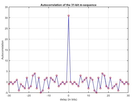
The autocorrelation of the 1m-sequence C above has a very strong distinctive peak, which can be used for frame synchronization purpose; see diagram below.

Finally, after differential encoding the bits in C using an initial symbol of 1, we have the preamble pattern P=[1 1 -1 -1 1 1 1 1 -1 -1 -1 1 -1 1 1 1 1 1 1 -1 1 1 1 -1 -1 1 -1 -1 1 -1 1 -1]
Please figure out why we want to impose differential encoding on the preamble pattern.
As for the data bits, they are the binary representation of a text message repeated 3 times. Lets use an example to illustrate this mapping process. Let the basic text message be (note the
“space” character at the end)
'The project provides tips about the final exam. '
After repeating it 3 times, we obtain the transmitted message
'The project provides tips about the final exam. The project provides tips about the final exam.
The project provides tips about the final exam. '
The above transmitted message contains altogether 48*3=144 characters. Each character is then mapped into an 8-bit pattern. This means the number of data bits is N2 = 144*8 = 1152. Notethat the reason for repeating the basic message 3 times is to mimic diversity reception, a technique commonly used in mobile communication systems to improve data reliability in a fading environment.
The mapping of each character in the transmitted message into a binary pattern is facilitated by the Matlab command “double”. This command translates each character into a decimal number between 0 and 127. For example, issuing the command double(‘T’) returns the decimal number 84, which in turn can be represented by the 7-bit pattern (1010100). In 1 format, this becomes (1 –1 1 –1 1 –1 –1). Finally, after differentially encoding with an initial bit of +1, we obtain the 8-bit representation of the character “T” as
(1 1 –1 –1 1 1 –1 1).
Note that with this 8-bit encoding format, you have the option of using differential detection aswell as more sophisticated techniques such as pilot-aided detection. One thing though, if you choose to use pilot-aided detection, remember to further differentially decode the decisions provided by the detector. Note differential decoding is NOT the same as differential detection.
The Matlab command that converts a decimal number back into a character is “char”. For example, the command char(104) gives you the character “h”.
Finally, the program that I used to generate the transmitted bits, called “tx.m”, are posted for cross-reference with this notes. Note that the notations used in the program are slightly different from the ones used in this notes.
Project Instructions
I had generated a basic message of length 100 characters (since each basic message is repeated 3 times, it means the size of the transmitted message is 300 characters, or 2400 bits). The corresponding file of received T/2-spaced samples (including junk bits and preamble) is rn100.mat. This data file is posted in the course webpage. Decode the message from this file. Note that if you divide the size of the array rn in the file rn100.mat by 2, you get the total number of bits, N, that are present in the received signal.
The parameters that are not known to you are
∈,N1, and N3
The absence of knowledge about ∈ means you have to do bit-timing estimation and compensation. The absence of knowledge about N1 means you have to do frame sync (using the preamble pattern). Not knowing N3, however, is not critical.
To recover the data contained in the received samples, the procedure you should adopt is to first do bit-timing estimation/compensation, followed by frame sync, and finally data detection.
The following results obtained for the sample message in the ‘tx.m’ program provide you a rough idea what to expect. They are for differential detection, with and without signal combining.


