CCE 201 engineering graphics and design
Assignment 4
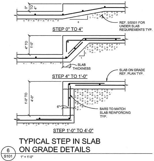
- The drawings below show three separate details for a reinforced concrete step, dependent upon the height of the step.
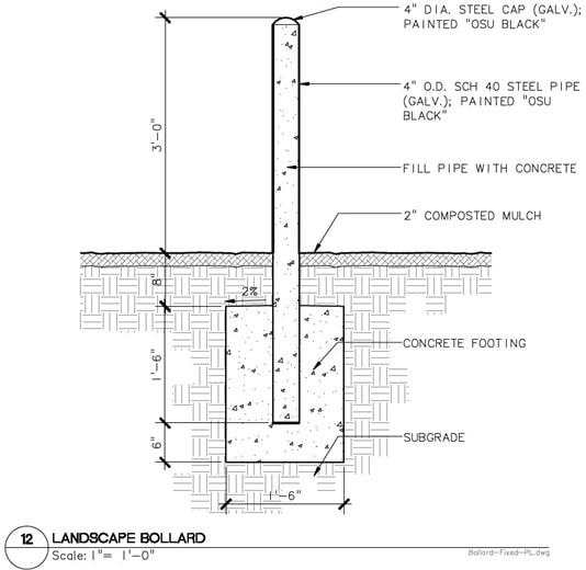
- Use your ANSI A-based template to recreate a version of this drawing in AutoCAD 2016.
- Use appropriate layers, annotations, scaling, text style, viewports, etc., as presented in class.
- Add at least the following layers to your drawings as “major objects” - Reinforcing steel, Concrete, Soil.
- Title Text ¼” height, upper case
- 1/8” font, upper case for other text

- Create the following layers and draw appropriate objects on them with the line weights listed to create a version of the drawing below:
{` Layer Line weights Concrete 0.35 mm; hatching pattern should match drawing provided Steel pipe 0.50 mm Dimensions 0.25 mm Text 0.25 mm Soil hatching pattern should match drawing provided Mulch hatching pattern should match drawing provided Border and title block 1.0 mm `}- Title at ¼” height, upper case
- 1/8” font, upper case for other text
- Center drawing in viewport
- Plot on your ANSI A-based template
- Note: Drawing is not plotted at the 1” = 1’-0” scale on this paper, but your AutoCAD drawing must be scaled properly (1” = 1’)


