BCD to 7 Segment Display Converter
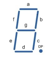
7-segment displays are commonly used in calculators, digital clocks, microwave ovens etc. There are 7 segments (hence the name) arranged in a rectangular pattern. By convention, each segment is identified by a letter from A to G as shown below. Some displays have a decimal point (including the Logic Circuit Display) but we not be using it.

Each segment has an input pin for turning that segment on. The problem is the input for the 7-segment display will normally be in Binary Coded Decimal format. In BCD, each digit from 0 to 9 is represented by a unique 4-bit binary number as shown below.
|
binary |
digit |
|
0000 |
0 |
|
0001 |
1 |
|
0010 |
2 |
|
0011 |
3 |
|
0100 |
4 |
|
0101 |
5 |
|
0110 |
6 |
|
0111 |
7 |
|
1000 |
8 |
|
1001 |
9 |
The binary numbers from 1010 to 1111 are not used in BCD. Binary Coded Decimal is not directly compatible with the input of the 7-segment display. Your task is to construct a converter that converts BCD to a format that can be used by the 7-segment display.
Each segment will have its own logic. (Recall that we used a Karnaugh map in class to develop a
reduced Boolean expression for segment A.)
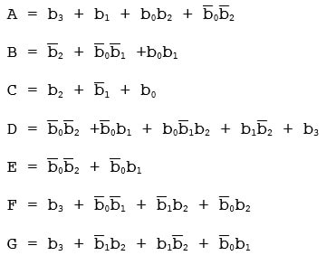
The input to the converter will be a 4-bit binary number with digits b3b2b1b0. The converter will have 7 output leads A to G corresponding to the input of the 7-segment display. (However, these output leads should be put through a 7-1 splitter, just to keep your circuit as neat as possible.) The reduced Boolean expression for each output lead is given below.

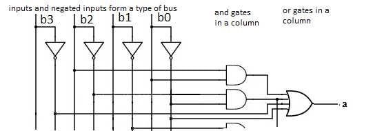
General Construction of a sum of products circuit.
The diagram below shows how a sum of products circuit (like we will be building) is generally constructed. The inputs and negated inputs form a type of bus on the left. All of the AND gates are arranged vertically in a column as shown. The OR gates appear in a column to the right of the AND gates.

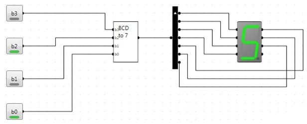
You should package your converter as a new logical circuit. Call it “BCD to 7”. Place a BCD to 7 circuit on main and connect it to a 7-seg display as shown below. Run your circuit.
You should be able to toggle the buttons on and off to test all of the BCD numbers from 0 to 9.
Save your converter as a circuit project file.


