MATLAB control instrumentation
SECTION A: Instrumentation
Part A1: Sensor Selection
The last 4 digits of student id is 2684
Therefore,
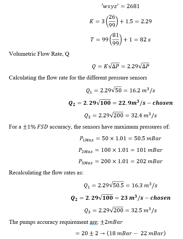
The most appropriate sensor is the differential pressure sensor with the range of 0-100mBar as described by the choices above.
Part A2: Transient Response
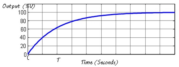
After switching the pump “on”, the step response takes T=82 s to reach 63.2% of its steady state value as shown in the figure. This indicates that the time constant of the pump is τ=82 seconds.
The rise time of the system is related to the time constant approximately by:
Tr=2.197 τ
Tr=2.197×82=180.154 s
As the pump is gradually switched on from “off” to “fully on”, the output response goes from transient state to a steady state value of 100 for large values of t. The step response, however, has no overshoot and as can be seen, the system is overdamped.
To calculate the bandwidth, we assume an oscilloscope that follows the following rule:
{`
Bandwidth ×Rise time=0.35
Bandwidth,BW=0.35/180.154=0.00194 dB
20 logBW=0.00194
logBW=0.00194/20=0.000097
BW=100.000097=1 rad/s
`}
Part A3: Filter Design
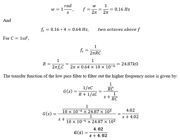
Using an RC filter design
Let:
C=10uF
Corner frequency is at two octaves above the bandwidth of the system at unity gain, K=1
Therefore:
SECTION B: Control
Part B1
Modelling
G(s)=Y(s)/U(s) =A/(s2+As+A.B)
The last 4 digits of student id is 2684
Therefore,
{`
'wxyz^'=2681
A=0.9(26/99)+0.5=0.74
B=2(81/99)+1=2.64
A=0.74,B=2.64
`}
The underdamped second order system is given by:
G(s)=0.74/(s2+0.74s+0.74(2.64))
=0.74/(s2+0.74s+1.9536)
Generally, the second-order transfer function takes the form of:
G(s)=(w02)/s2+2ζwo s+w20
Where w0 is the natural frequency, ζ is the damping ratio.
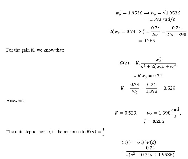
Therefore, by comparison of the 2 equations
Plotting in MATLAB
Part B2: Control
Part (i)
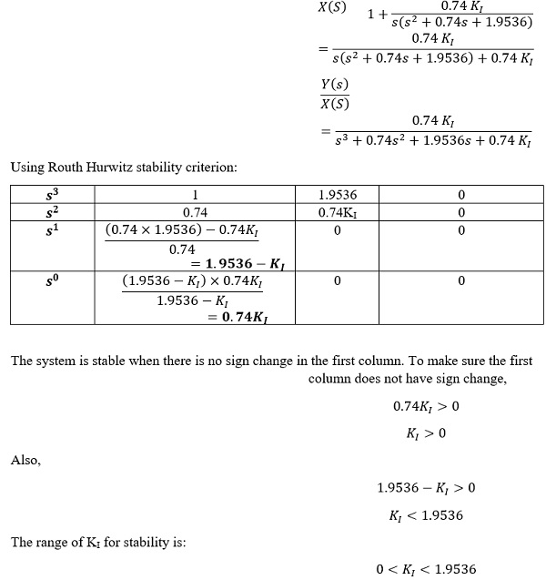
Finding the closed loop system transfer function
Forward path/Open loop transfer function
Y(s)/E(s) =KI/s (G(s))
=(0.74 KI)/(s(s2+0.74s+1.9536))
Closed loop transfer function
{`
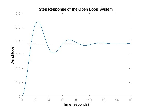
clear
clc
s=tf("s");
G=0.74/(s2+0.74*s+1.9536);
figure (1)
step(G)
title("Step Response of the Open Loop System")
`}
Part (ii)
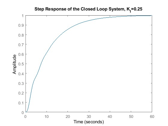
Choosing a KI of 0.25 which is in the range of , the step input response is obtained using MATLAB.
{`
%Let Ki=0.25 since for stability 0< Ki <1.9536
Integral_Controller=0.25/s;
G1=Integral_Controller*G;
T=feedback(G1,1);
StableOrNot=isstable(T)
figure(2)
step(T)
title("Step Response of the Closed Loop System, K_I=0.25")
`}
StableOrNot =
logical
1
