ITNE2003 Lab Tutorial 6
{`
ITNE2003
Install, Configure, Operate and Troubleshoot Medium-Sized Networks
Lab Tutorial – 6 of Lesson -6
Victorian Institute of technology
`}
InterVLAN Routing LAB
Task Assignment
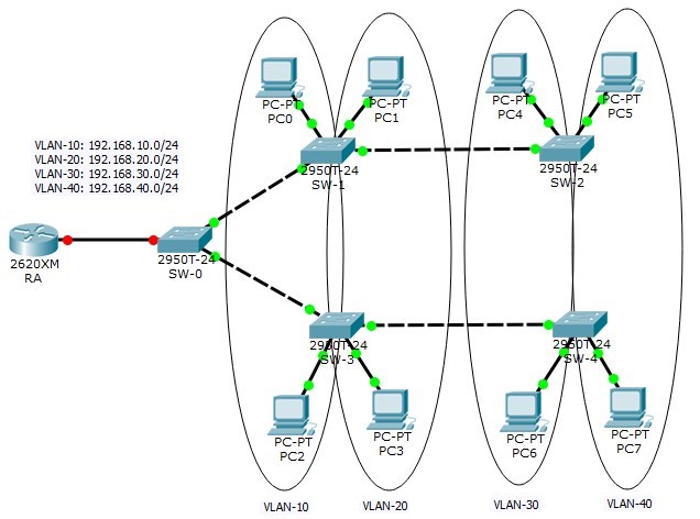
Network Address Plan
|
VLAN-10 | ||
|
Allocated subnet |
192.168.10.0/24 | |
|
Network Address |
192.168.10.0 | |
|
Broadcast Address |
192.168.10.255 | |
|
SW-1: F0/1 |
To PC0: 192.168.10.2 | |
|
SW-3: F0/1 |
To Pc2: 192.168.10.3 | |
|
VLAN-20 | ||
|
Allocated subnet |
192.168.20.0/24 | |
|
Network Address |
192.168.20.0 | |
|
Broadcast Address |
192.168.20.255 | |
|
SW-1: F0/2 |
PC1: 192.168.20.2 | |
|
SW-3: F0/2 |
PC3: 192.168.20.3 | |
|
VLAN-30 | ||
|
Allocated subnet |
192.168.30.0/24 | |
|
Network Address |
192.168.30.0 | |
|
Broadcast Address |
192.168.30.255 | |
|
SW-2: F0/1 |
PC4: 192.168.30.2 | |
|
SW-4: F0/1 |
PC6: 192.168.30.3 | |
|
VLAN-40 | ||
|
Allocated subnet |
192.168.40.0/24 | |
|
Network Address |
192.168.40.0 | |
|
Broadcast Address |
192.168.40.255 | |
|
SW-2: F0/2 |
PC5: 192.168.40.2 | |
|
SW-4: F0/2 |
PC7: 192.168.40.3 |
Switch and router interface description table
This table helps network engineers to quickly identify the routing direction of each interface in a complex network environment.
|
SW-1 | ||
|
Interface FastEthernet0/1 |
ACCESS |
VLAN-10 |
|
Interface FastEthernet0/2 |
ACCESS |
VLAN-20 |
|
Interface FastEthernet0/3 |
TRUNK |
NATIVE VLAN-100 ALLOWED: VLAN-10, 20, 30, 40 |
|
Interface FastEthernet0/4 |
TRUNK |
NATIVE VLAN-100 ALLOWED: VLAN-10, 20, 30, 40 |
|
SW-2 | ||
|
Interface FastEthernet0/1 |
ACCESS |
VLAN-30 |
|
Interface FastEthernet0/2 |
ACCESS |
VLAN-40 |
|
Interface FastEthernet0/3 |
TRUNK |
NATIVE VLAN-100 ALLOWED: VLAN-10, 20, 30, 40 |
|
Interface FastEthernet0/4 |
Not connected | |
|
SW-3 | ||
|
Interface FastEthernet0/1 |
ACCESS |
VLAN-10 |
|
Interface FastEthernet0/2 |
ACCESS |
VLAN-20 |
|
Interface FastEthernet0/3 |
TRUNK |
NATIVE VLAN-100 ALLOWED: VLAN-10, 20, 30, 40 |
|
Interface FastEthernet0/4 |
TRUNK |
NATIVE VLAN-100 ALLOWED: VLAN-10, 20, 30, 40 |
|
SW-4 | ||
|
Interface FastEthernet0/1 |
ACCESS |
VLAN-30 |
|
Interface FastEthernet0/2 |
ACCESS |
VLAN-40 |
|
Interface FastEthernet0/3 |
TRUNK |
NATIVE VLAN-100 ALLOWED: VLAN-10, 20, 30, 40 |
|
Interface FastEthernet0/4 |
Not connected | |
|
SW-0 | ||
|
Interface FastEthernet0/3 |
TRUNK |
TO ROUTER RA NATIVE VLAN-100 ALLOWED: VLAN-10, 20, 30, 40 |
|
Interface FastEthernet0/1 |
TRUNK |
NATIVE VLAN-100 ALLOWED: VLAN-10, 20, 30, 40 |
|
Interface FastEthernet0/2 |
TRUNK |
NATIVE VLAN-100 ALLOWED: VLAN-10, 20, 30, 40 |
|
Router RA | ||
|
Interface FastEthernet0/0 |
NO IP ADDRESS |
InterVLAN routing |
|
Interface FastEthernet0/0.10 |
192.168.10.1/255.255.255.0 |
TO VLAN-10 |
|
Interface FastEthernet0/0.20 |
192.168.20.1/255.255.255.0 |
TO VLAN-20 |
|
Interface FastEthernet0/0.30 |
192.168.30.1/255.255.255.0 |
TO VLAN-30 |
|
Interface FastEthernet0/0.40 |
192.168.40.1/255.255.255.0 |
TO VLAN-40 |
Network Topology
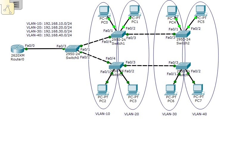
Before we start to configure the above network, we need to create the topology in our Packet Tracer simulation tool. Based on the above table we can build our network as follows:
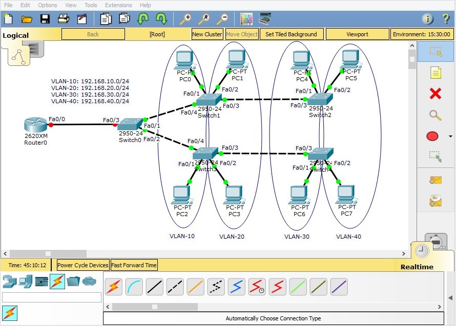
**TIP: As explained in previous guidelines, it’s recommended to have information about your network in your topology area. In the above figure, four different VLANs are distinguished by blue ellipse. In order to use drawing tools to separate different parts of your network, click the drawing tool on the right pane of Packet Tracer.
Seperating VLANs
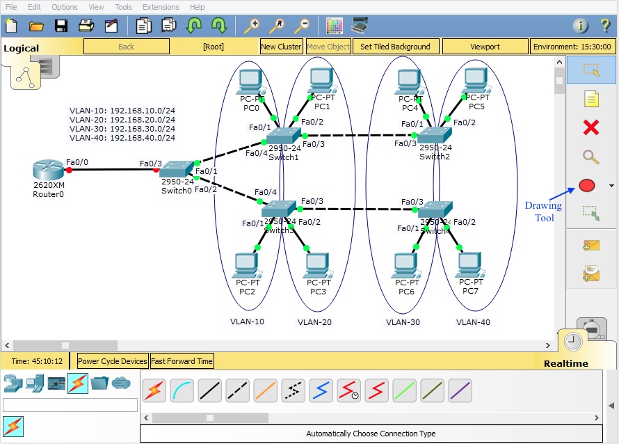
By clicking on the icon, a new window will pop up, in which you can select your tool.
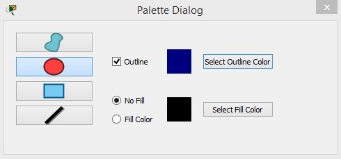
In this window you can select the shape you want to insert into your topology area as well as the color of it.
Configuration
**Please notice that we have skipped some administrative settings of our network devices (password, banner…) in this lab for brevity. You can configure them in your simulation tool to have a complete configuration of the network.
Switch Configuration
Hostname

VLAN Configuration
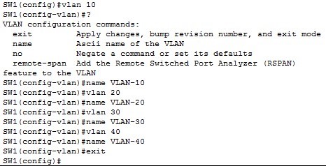
In this scenario we have 4 VLANs (VLAN-10, VLAN-20, VLAN-30 and VLAN-40), as depicted in the figure. These VLANs should be defined on all our switches. Starting with switch 1(SW-1), following configuration shows how to configure VLANs on a switch.
Interface Configuration
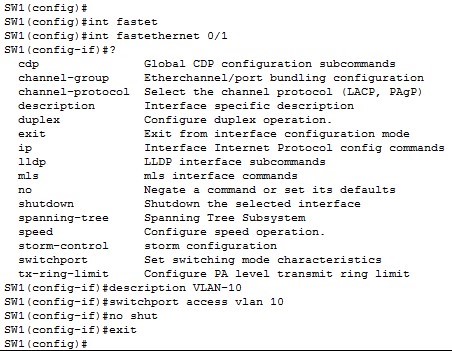
Since interface FastEthernet 0/1 and FastEthernet0/2 are connected to hosts, we configure them as access interfaces. Following figure shows the configuration.
FastEthernet 0/1
FastEthernet0/2

Interfaces FastEthernet 0/3 and FastEthernet 0/4 are connected to switches (SW2 and SW0 respectively). So they should be configured as trunk.
FastEthernet 0/3

FastEthernet 0/4

Save the running configurations
Finally, we save the running configuration to NVRAM so switches can load the configuration automatically next time when power on.

Repeat these steps for switches SW-2, SW-3, SW-4 and SW-0
InterVLAN Configuration on Router
Like all other network devices, we first configure the hostname of our Router.
Hostname

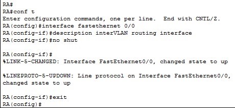
Physical Interface Configuration
Virtual interface configuration
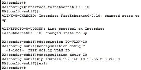
You have to repeat the above configuration for VLAN-20, 30 and 40.
After you have successfully configured the router interfaces, the connection between the interfaces are established and shown in green colour. Following figure shows the final status of our network.
Save the running configurations
Finally, we save the running configuration to NVRAM so the router can load the configuration automatically next time when power on.

PC Configuration
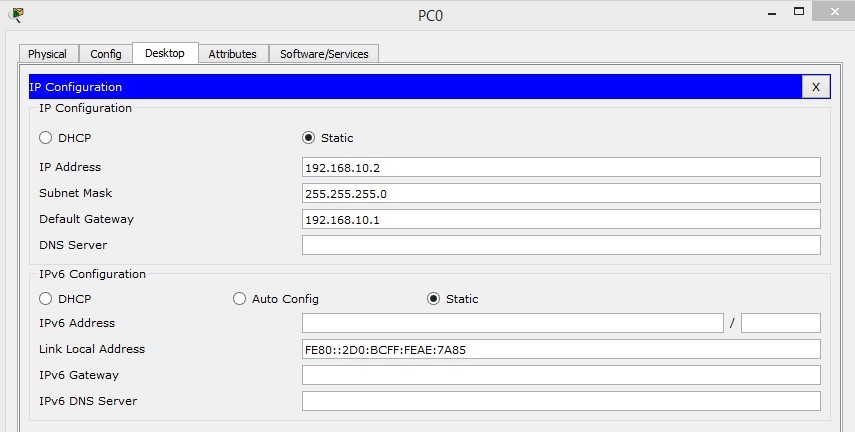
Now that we have configured routers and switches, we need to assign IP addressed to PCs. The default gateway would be the IP address of router’s sub-interfaces.
