ITNE2003 Lab Tutorial 5
ITNE2003
Install, Configure, Operate and Troubleshoot Medium-Sized Networks
Lab Tutorial – 5 of Lesson -5
Victorian Institute of technology
Task Assignment
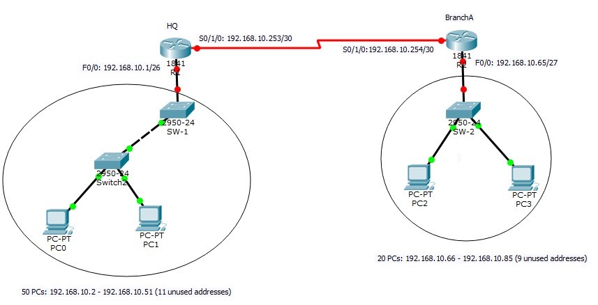
IP Network to be subnetted: 192.168.10.0/24
- HQ: 50 PCs
- Branch A: 20 PCs
Network Address Plan
|
Head Quarter | |
|
Total number of IP address required in details Number of IP addresses allocated for PCs Number of IP addresses allocated for router interface Number of IP addresses reserved for future use |
53 50 1 11 |
|
Allocated subnet |
192.168.10.0/26 |
|
Network Address |
192.168.10.0 |
|
Broadcast Address |
192.168.10.63 |
|
Valid host address range (can be used to assign to PCs, servers, IP phones, printers etc.) |
192.168.10.1 – 192.168.10.62 |
|
Branch A | |
|
Total number of IP address required in details Number of IP addresses allocated for PCs Number of IP addresses allocated for router interface Number of IP addresses reserved for future use |
23 20 1 9 |
|
Allocated subnet |
192.168.10.64/27 |
|
Network Address |
192.168.10.64 |
|
Broadcast Address |
192.168.10.95 |
|
Valid host address range (can be used to assign to PCs, servers, IP phones, printers etc.) |
192.168.10.65 – 192.168.10.94 |
|
R1-R2 subnet | |
|
Total number of IP address required in details Number of IP addresses allocated for router interfaces Number of IP addresses reserved for future use |
4 (for IOS compatibility) 2 0 |
|
Allocated subnet |
192.168.10.252/30 |
|
Network Address |
192.168.10.252 |
|
Broadcast Address |
192.168.10.254 |
|
R1 and R2 Interface IP address |
192.168.10.253 and 192.168.10.254 |
Address allocation map
|
HQ Network |
192.168.10.0 192.168.10.63 |
|
Branch A |
192.168.10.64 192.168.10.95 |
|
Unused addresses | |
|
R1-R2 subnet |
192.168.10.252 192.168.10.255 |
Router interface description table
This table helps network engineers to quickly identify the routing direction of each interface in a complex network environment.
|
Router R1 (HQ) | ||
|
Interface FastEthernet0/0 |
192.168.10.1/255.255.255.192 |
To HQ network |
|
Interface FastEthernet0/1 |
None |
Not connected |
|
Interface Serial0/1/0 |
192.168.10.253/255.255.255.252 |
To branch A |
|
Router R2 (Branch-A) | ||
|
Interface FastEthernet0/0 |
192.168.10.65/255.255.255.224 |
To Branch A network |
|
Interface FastEthernet0/1 |
None |
Not connected |
|
Interface Serial0/1/0 |
192.168.10.254/255.255.255.252 |
To HQ |
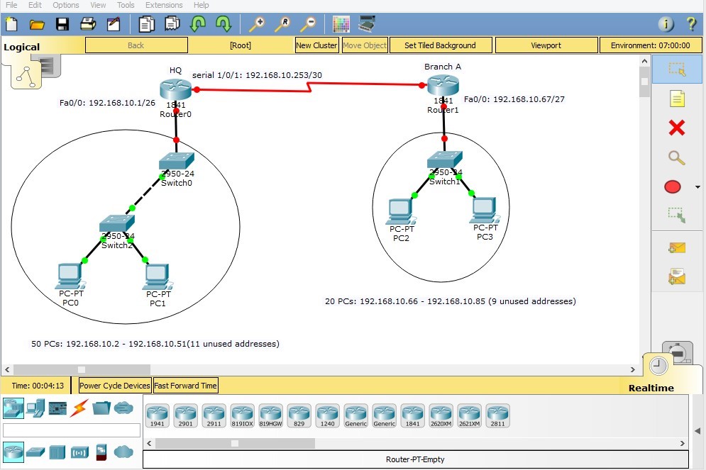
Network Topology
Before we start to configure the above network, we need to create the topology in our Packet Tracer simulation tool. Based on the above table we can build our network as follows:
Configuration
Router1 Configuration
Hostname

Interface Configuration
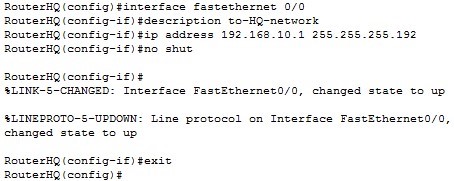
As our topology indicates, R1 has two connected interfaces: FastEthernet 0/0 and Serial 0/1/0. It also has FastEthernet 0/1 that is unused in this scenario. Here is how we configure these interfaces.
FastEthernet 0/0
FastEthernet0/1

Interface FastEthernet 0/1 is unused in this scenario, so it’s better to shut down the interface. In real world, shutting down unused interfaces helps having better security in network.
Serial 0/1/0
Interface Serial 0/1/0 in connected to “Branch A” router and it needs an IP address from
192.168.10.253/30 subnet to be operational. We also need to check if this interface is DCE/DTE. As discussed in previous assignments, for DCE interfaces “Clock rate” should be configured on router.
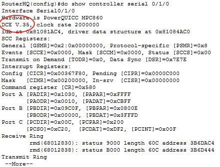
And the configuration for serial 0/1/0 would be:

Router 1 access protection

Save Configuration

Router2 Configuration

Interface Configuration
FastEthernet 0/0
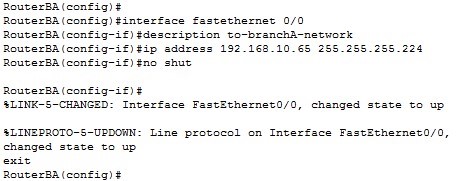
FastEthernet0/1

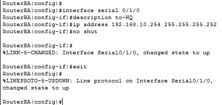
Serial 0/1/0
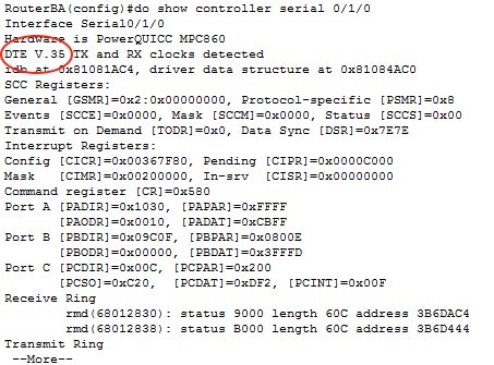
As you can see from the output of “show controller” command on RouterBA, serial 0/1/0 on that router is DTE and there is no need to set clock rate on it.
Following figure shows serial 0/1/0 configuration on RouterBA:
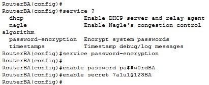
Router 2 access protection
Save configurations
Finally, we save the running configuration to NVRAM so routers can load the configuration automatically next time when power on.

After you have successfully configured the two router interfaces, the connection between the interfaces are established and shown in green colour.
