ITNE2003 Lab Tutorial 3
{`
        ITNE2003
        Install, Configure, Operate and Troubleshoot Medium-Sized Networks
        Lab Tutorial – 3 of Lesson -3
        Victorian Institute of technology
        `}
- Implement administrative configuration on Cisco IOS devices
Task Assignment
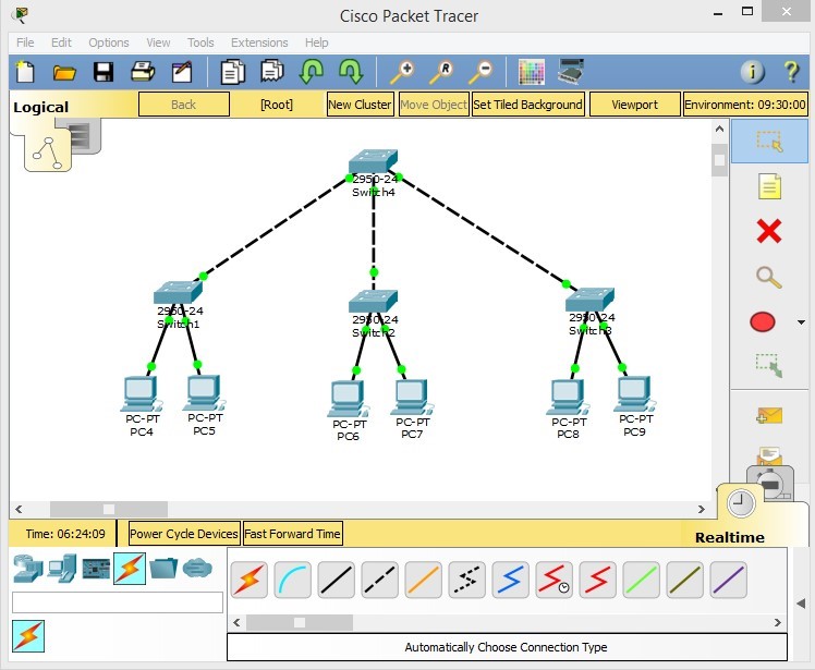
Implement the following network diagram on Cisco Packet Tracer
- Configure IP addresses for all PCs
- Configure administrative settings for all switches
- Verify access for all switches and PCs
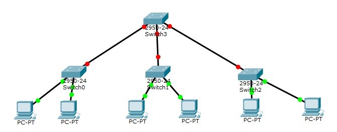
1 Create the topology
Add devices to topology area and connect them to eachother. In this task we need four layer 2 switches (e.g. Cisco 2950) and six hosts (PCs).
To add switches to your topology area simply go to Network devices -> Switches and choose a 2950 switch.
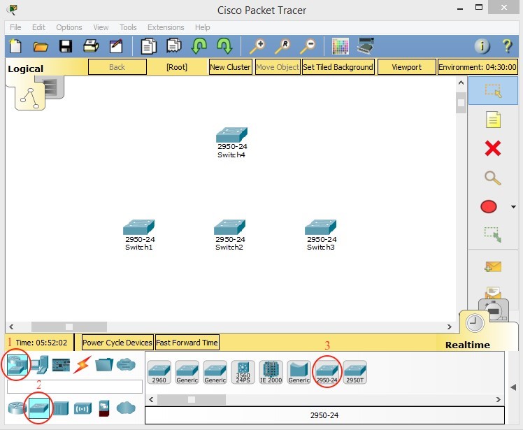
To connect switches to eachother, you need to use Cross-Over cable. To do so, go to “Connections” category, select “Copper Cross-Over” connection and choose the interfaces that you want to connect on each switch.

Another option is to choose the first option from the left, “Automatically choose connection type”. In this case the appropriate cable and interface will be selected each time you decide to connect devices together.
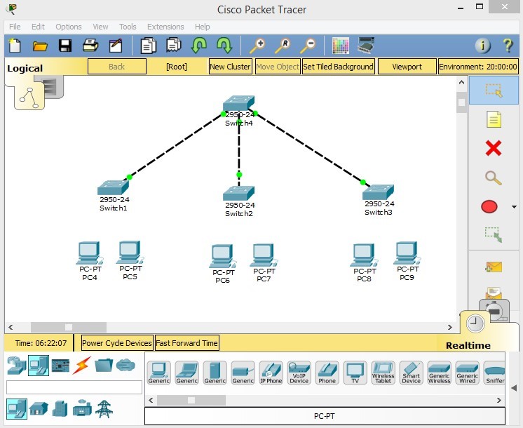
Last but not least you need to connect PCs to switches. To do so, Copper Straight-Through cable needs to be used.

2 Determine IP addresses and subnet masks to be used
Before configuring your devices with IP/Mask, you need to define your scope of IP addresses.
**It is recommended to write the Network ID/mask of each device/interface next to it, so you can keep track of all the IP addresses used in your scenario. To do so:
- Click on the “Place Note” icon (second icon from the top) in the right toolbar. Then click on the topology area and type the IP address/mask or any information that you need to add to your scenario.
* If you cannot see the right pane, go to View -> Toolbars and tick the “Right Toolbar”.
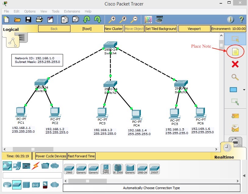
As it is shown in the figure, the IP/Mask that is used in this example is:
192.168.1.0
255.255.255.0
3 Assign IP addresses
To assign IP addresses to PCs:
Click on the intended PC -> IP Configuration -> Desktop tab
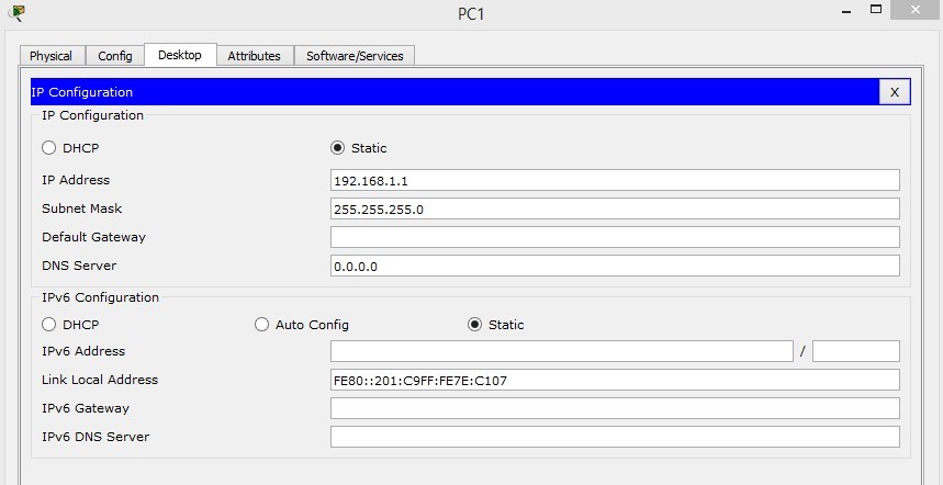
You need to repeat this for other 5 hosts as well.
4 Configure administrative settings
These settings include setting name, password, banners and interface descriptions
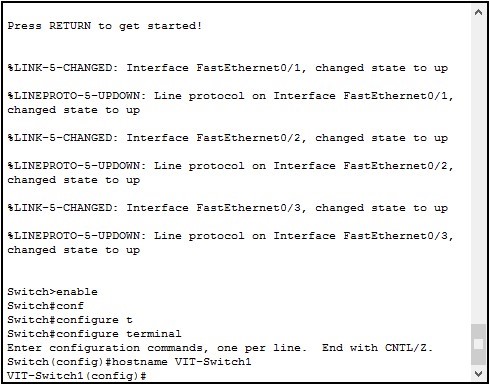
The following figures show required commands for each administrative setting as well as the correct mode that these commands should be issued.
4.1 Name
4.2 Password

4.3 Banner
*In packet tracer and with 2950 switch you can only set “motd” banner

4.4 Descriptions

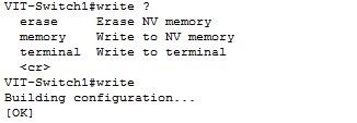
5 Save the configuration
For saving your current configuration to NVRAM of your device, following command should be issued:
The alternative command is:
6 Verify the configuration
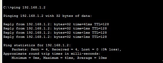
1.1 Ping
6.2 Show commands to verify the status of the network
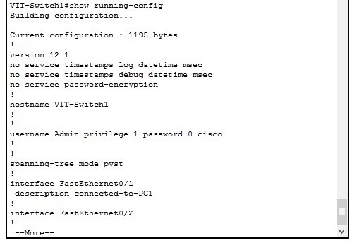
6.2.1 Show running-config
To see you current configuration you can use this command.
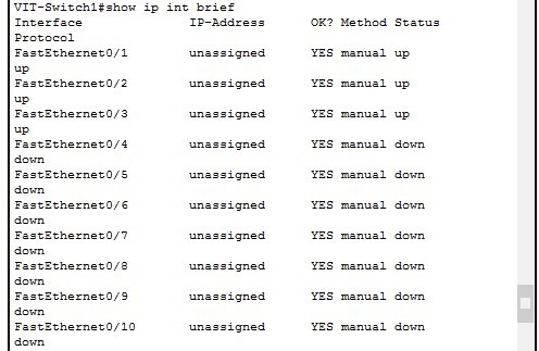
6.2.2 Show ip interface brief
To have an overview of your interfaces and their status, this is a handy command.
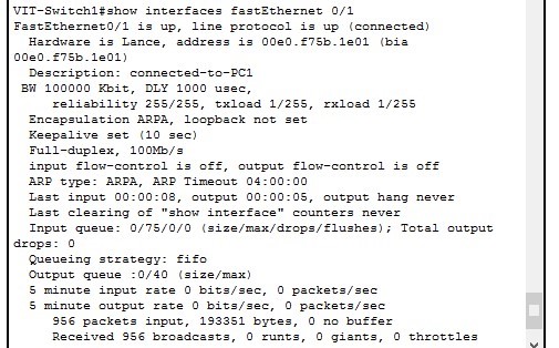
6.2.3 Show interfaces
To see the details of your interfaces, you can use this command.
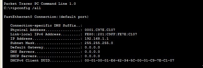
6.2.4 IPconfig
Use this command on your PC to see the IP configuration of your PC.
