ENEC20003 Numerical Analysis Term 2 2019
Assignment
Numerical Analysis
ENEC20003 Term 2 2019
Numerical Simulation Project:
Simulate a Fixed-ring consolidation test on a clay sample for bath loading and unloading stages using Geostudio Sigma/W package. Assume the following.
Sample diameter: 75mm
Sample Height: 20mm
Bulk Unit weight of the sample: 19 kN/m3
Cohesion: 40kPa
Internal Friction angle: 24
Dilation angle: 0
Module of Elasticity (E): 10MPa
Poisson Ratio: 0.334
Permeability in the satursted condition: 1E-12m/sec
Loading stages: Day 1: 12.5 kPa, Day 2: 25, Day 3: 50kPa, Day 4: 100 kPa, Day 5: 200 kPa
Unloading stages: Day 6: 100 kPa, Day 7: 50 kPa, Day 8: 25 kPa
If you require more parameter, assume a reasonable value and state it in your solution.
| Time (day) | Applied Surcharge stress (kPa) |
| 0 (in situ analysis) | 0 |
| 1 | 12.5 |
| 2 | 25 |
| 3 | 50 |
| 4 | 100 |
| 5 | 200 |
| 6 | 100 |
| 7 | 50 |
| 8 | 25 |
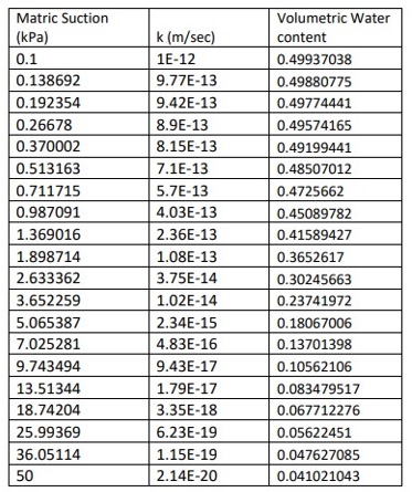
Use the following hydraulic conductivity and volumetric water content functions:

Hints
- Use a material category of Effective Parameter with PWP Change for the consolidation test;
- Use Elastic-Plastic (PWP change) Material model to simulate the clay;
- Define a step loading boundary function to apply the surface loading;
- Assume an isotropic clay;
- Create one analysis foe each day and set the new analysis as a child of the previous analysis;
- Please note that the water table is always at the top of the sample.
Please note that there will be two porous stones at the top and bottom of the sample for providing drainage to the sample.
Therefore, you should add a hydraulic boundary condition of (zero pore-water pressure) to both the top and bottom of the sample.
Note: Make reasonable assumptions if needed and state your assumptions clearly in your report.
- Model Geometry (Max. 1-page image)
- Model Materials (Max. 1-page text)
- Boundary condition and analysis tye (Max. 2-page text/graph/image)
- The shape of the deformed sample (Max. 1-page image)
- Draw a graph of the displacement of the top center of the sample with time (day)
- Draw a graph of the excess pore-water pressure at the mid-layer center of the sample over time (day).
- Draw a graph of the effective stress at mid-layer center of the sample over time (day)
Task:
Model the above problem using Geostudio 2018 and Prepare a report with the following components:
The report must be submitted in the current MS Word file including the answers to the above questions. You should also upload your GeoStudio into a Google drive and add the link to the report.


