Effect of various Passive Techniques on Heating and Cooling Load of Buildings
Effect of various Passive Techniques on Heating and Cooling Load of Buildings and Reduce at least 50% load by applying Passive Techniques
Abstract:
The human comfort level depends upon some suitable environmental conditions i.e. temperature and humidity etc. and air conditioning systems help to maintain these suitable conditions. In this study, suitable building design is presented along with the weather conditions of its surrounding. The model of the building was designed using Ecotect software and heating and cooling loads for the structure were calculated. These heating and cooling loads were reduced to about 53% using passive techniques for the building design. A vapor absorption system was designed based on these reduced heating and cooling loads with proper specifications of each working component. Also, a comparison of VAS and VCC was made based on their cost as well as their environmental effects and a suitable conclusion was made in this regard.
Introduction:
Human comfort depends upon the environmental conditions of the surrounding. Certain environmental conditions are much more suitable to humans i.e. 20oC -20oC temperature and humidity level of 40%-60%. as compared to other environmental conditions. To obtain such conditions, scientific methods are available. Also, developing countries like Pakistan face much of the power crises, to attain human comfort in the presence of such crises passive techniques are available which helps to reduce the cooling and heating loads of the structure. In this complex engineering problem, such passive techniques are presented along with the design of the vapor absorption system which is one of the major sources of human comfort these days.
In the first part of CEP factors affecting the heating and cooling loads of building are provided along with a building was designed for weather conditions of Karachi, Pakistan. The building model was a replica of the original building. The heating and cooling loads for the given model were calculated using Ecotect software. Initially, the building was designed using general materials. Based on these heating and cooling loads the tons were calculated for the model. In the second part of CEP passive techniques were applied to reduce these heating and cooling loads to about 50%. For this purpose, insulating material was used in the walls, ceilings, roof, and floor of the building. Moreover, double glazed windows were also used for this purpose along with the proper orientation of the building.
In the third part of this CEP number of tons was calculated based on these heating and cooling loads and a vapor abortion system was designed. The mass flow rate of the refrigerant and solution, heat absorbed and rejected by various components of this vapor absorption system, and pressure and temperature requirements of condenser and evaporator were calculated. In the fourth and fifth part, a comparison of the cost was made between VAS and VCC, and the environmental effects of these systems were made. Based on the data available in the market a suitable conclusion was made.
Literature Review:
Impact of Orientation:
Planners of the building help to approach the best design of the building. For this purpose, the orientation of the building matters a lot. Different decisions are made before the building design to minimize the effective energy usage. In these decisions, the orientation of the building has a very crucial part. Also, some other factors help to attain solar effective energy usages like walls, windows, their locations, and ceilings, etc. these parameters are critical but the effectiveness matters a lot. In case of the effectiveness, the orientation has a major part in it[1].
Most of the planners take recommend the orientation of the building along the axis of the building. Also, some of the planners make the perpendicular to the axis. Also, these orientations are based on taking the different parameters into the account. These parameters are the drainage, street ways, sewage, roads, views, etc. but since here we are talking about the energy usage and heat transfer as well passive solar techniques as the major concerns then we are taking the orientation axis just not others parameters[1].
In the curved streets, that are present in abundance in most of the countries, there is always the axis that is the dominating. That determines the orientation of the building. Since the plan is to make the effective use of solar consumption so most of the windows are the streets facing and sky facing[1].
Zoning of the building, streets ways, blocks, and the building orientation is the most important initials of the architects. They are all presented in the initials design plans. Designs of different orientations having various climate-changing parameters, window wall ratios, thermal energy, etc. The simple and basic way of the effective way of the savings is the orientation. It has a potential decreasing effect on energy consumption[1].
Impact of Insulation:
In many countries the having the severe climatic conditions the different kinds of insulations are being applied in the wall as well as the roof structure. These are applied to get the maximum comfort zone of the people living inside it. Different thickness ranges are applied to the insulation purpose regardless of the economic factor. Also, the orientation parameters for the wall insulation is not usually taken into account. For the insulation purpose, some of the pre estimations are taken into account. Firstly, for the estimation of yearly transmission loads of the cooling and heating values of the building or the location area is calculated. Roof insulations of thickness ranges are of 5cm to 7 cm and are used to get the desired comfort level inside the house or the building. For the optimum insulations, the lifetime of the building is taken, which is 30 years. Annual heating and the cooling load's transmission of the building are the main input parameters that are used for the thermal insulation analysis for the roof structure[2].
This has been attained from the literature that the application of the insulations helped a lot in increasing the comfort level. For cooling loads calculations, different types of heat flow are taken in the literature. The transients and other flow rates are being discussed here. In which they applied the different methodologies and different software techniques to calculate the cooling and heating load variations that attained due to the different parameter insulations of roof and walls[2].
Similarly, this heat flow and energy consumption topics related to the cooling loads of the heating value of the building have been a favorite part of the research. Analytical modeling then the validation of the results for the usage of the insulations with various parameters taken in the account has shown in the literature that different insulation ranges have helped in energy consumptions and dealing with the cooling and heating loadings[2].
Impact of Window and Wall Ratios:
Façades are the front-facing windows of the building and the main source of the entrance of the light into the house. These façades have an important impact on the annual energy consumption and heating loads. Also, in the same way, they are the main source of the cooling loads as well. Different case studies in the literature show the variations in the calculations of the annual energy consumption of the building with the reference of the windows. Different aspects of the windows are used in these case studies of the research that are the shape, size, and window position on the wall. Window to wall ratios is also considered as one of the main factors in these research papers[3].
Solar radiations making their way in the building matters a lot in determining the annual energy usage and the cooling load's effects in the building. And for the architect’s rule point of view, there are different aspects one must be considered for comfortable living standards. The fresh air intake in the building is one of them and the windows are the source of the fresh air. The energy demand and the lighting demand is influenced by the size and the position of the window[3].
Different material of the windows with different sizes have different U values, is that the conductance values. In one of the research paper, they have performed the simulation models in the Wuhan city to check the optimal window and wall ratio performance. They check the heating load values and cooling energy demand. Also along with the window size and its locations, they check other parameters like materials and orientation. Power consumption of air conditioners and the total energy consumption is studied in the different research papers. And the different aspect of the window wall ratio on different buildings in different orientation is done. It concluded that the energy consumption of the building is dependent on the window wall ratios as well as the material of the windows and their location[3].
Impact of Double Glazing Windows:
Different activities and various ways are being adopted to get house comfort. Different parameters and variables are taken into account for the calculation of the optimization of the data. To get the thermal heating load conditions acceptable different times of the days are taken in the reference to check the best comfort level in the building. The design process and the simulation the models to analyze the data and access whether which activity is best for the annual energy consumption. Glazing of the windows is one of them. Optimization of the glazing of the windows is the most crucial task[3, 4].
To meet the building and the commercial offices having big windows energy-related needs are very important because there we are very much concerned about the working environment of the office. The need for comfort and proper air and energy balance is a potent part of the office environment. So the working of choosing the types of glazing windows, the percentage of the glazing area[3, 4].
Glazing of the windows is the potential factor in the buildings that are directly related to energy consumption. There is the energy-saving space if the glazing of the windows applied with the optimized pattern. In the literature case studies of different areas like Malaysia, Greece, and Wuhan have been discussed. And taking the different parameters and different shapes of windows with a different area of glazing has been studied. Almost every case study helped in the energy-saving conclusive remark for the glazing of the window. A similar pattern of energy-saving is attained throughout the summer and the winter months[3, 4].
Building Design:
Dimensions:
An office was designed to have an orientation. The location of the design model was selected in Karachi, Pakistan i.e. weather conditions of Karachi were selected. The area of the office designed was selected to be 668.000 m2 i.e. square area. The office has a front door having south in front of the door and north back to the door. The door has a width of 1m and a height of 2m. There are two windows of the office which are oriented in the east-west position i.e. one at the eastern wall and the other at the western wall. The dimensions of the windows are selected to be 2 m × 2 m = 4 m2. The windows are in the middle of the walls. There is also a void at the top of the office having dimensions 2m×2m = 4m2. There is also a room on top of the office for keeping files and other important data. The above room has four windows having area 2 m × 2 m = 4 m2. The 3D- model of the office is given below.
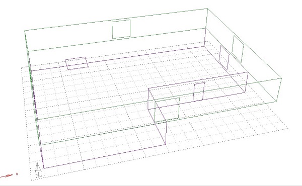
Figure 1: 3D-Office Model
Design Conditions:
The internal design conditions are light business suits, with the internal humidity level of the room to be 40% and airspeed to be 0.5 m/s. the lighting level of the room is 300 lux. The rooms are designed for typical office usage i.e. 21 persons for lower portion and 10-15 people in the upper portion. The average biological heat output level is sedentary-70W. The sensible and latent heat gains are selected to be 5 W/m2 and 2 W/m2 respectively which are the values of both lighting and small power loads per unite floor area. The values of exchange of air between zone and outside environment are selected to be 0.5m/s and wind sensitivity values are 0.25 Air changes/hr.
In the first case, only the natural ventilation system for the room is considered with 95% efficiency. The comfort temperature level is selected to be 20-25oC which is the average human comfort temperature. The hours of operation of the office are 8 am to 5 pm on weekdays and the office is closed on weekdays.
The door of the office is glass sliding door. All windows of the office are made up of double glazed- timber frame of upper as well as of the lower portion. The roofs of the office are made up of concrete asphalt type whereas ceilings of the office are made up of suspended concrete ceiling. The floors of the office are made up of concrete Slabs. The lights of the office are turned on and off manually. The room uses a mechanical mechanism for ventilation purpose and its extract fan has a capacity of 3 m3/ls. The walls of the office are made up of a brick timber frame. A complete visualization of the office is shown below.
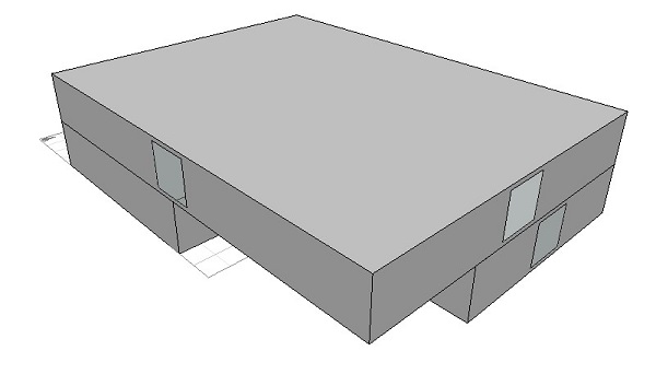
Figure 2: Office with Selected Materials
Results:
The monthly load/discomfort level for the given design conditions are provided in figure No. 3. The below graph is between heating and cooling loads and months. As can be seen from the figure that the office heating loads during the months of November-March and cooling loads during the months of May-September.
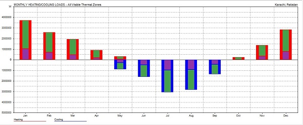
Figure 3 Monthly Loads/Discomfort
Table 1:
|
Sr. No. |
Months |
Heating |
Cooling |
Total |
Tons |
|
W |
W |
W | |||
|
1 |
Jan |
5199390 |
0 |
5199390 | |
|
2 |
Feb |
3756243 |
0 |
3756243 | |
|
3 |
Mar |
2934779 |
0 |
2934779 | |
|
4 |
Apr |
1421429 |
0 |
1421429 | |
|
5 |
May |
568428 |
745326 |
1313754 | |
|
6 |
Jun |
26495 |
1355463 |
1381958 | |
|
7 |
Jul |
0 |
2761000 |
2761000 | |
|
8 |
Aug |
0 |
2517620 |
2517620 | |
|
9 |
Sep |
47506 |
1107254 |
1154760 | |
|
10 |
Oct |
451279 |
0 |
451279 | |
|
11 |
Nov |
2096264 |
0 |
2096264 | |
|
12 |
Dec |
4053146 |
0 |
4053146 | |
|
TOTAL |
20554960 |
8486664 |
29041624 |
8.415 | |
Max Heating: 44648 W at 09:00 on 19th December
Max Cooling: 29588 W at 17:00 on 9th July
Building Design using Passive Techniques:
The second office model was designed using passive techniques. Shades were introduced on windows and doors having dimensions of 0.5m×2m = 1.00 m2 and 0.5m×1m = 0.50 m2. The ceiling is replaced with insulation called plaster insulation suspended. All the walls of the office are replaced with double brick cavity renders which are more isolating to heat as compared to previous ones. The roof is made from plaster foil heat retention ceramic tiles with more heat-absorbing capacity and is a green roof technique. The floor is replaced with a timber floor carpeted suspended[5]. The results of the analysis are given below.
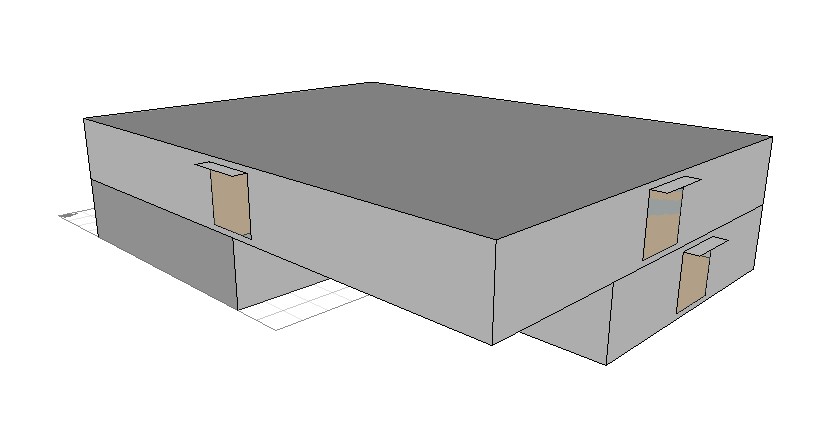
Figure 4: Office with Selected Materials
Results:
With the applications of passive techniques to the office, the total heating and cooling loads have been reduced to 13467170 W as compared to 29041624 W which is about 53.62% reduction in heating and cooling loads of the building. The results obtained through the analysis are given below:
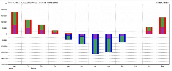
Figure 5: Monthly Load Distribution
Table 2
|
Sr. No. |
Months |
Heating |
Cooling |
Total |
Tons |
|
W |
W |
W | |||
|
1 |
Jan |
2195396 |
0 |
2195396 | |
|
2 |
Feb |
1431098 |
0 |
1431098 | |
|
3 |
Mar |
939543 |
0 |
939543 | |
|
4 |
Apr |
363426 |
0 |
363426 | |
|
5 |
May |
78916 |
538055 |
616972 | |
|
6 |
Jun |
0 |
1000669 |
1000669 | |
|
7 |
Jul |
0 |
1936223 |
1936223 | |
|
8 |
Aug |
0 |
1767043 |
1767043 | |
|
9 |
Sep |
749 |
814729 |
815478 | |
|
10 |
Oct |
28752 |
2861 |
31613 | |
|
11 |
Nov |
711301 |
0 |
711301 | |
|
12 |
Dec |
1658409 |
0 |
1658409 | |
|
TOTAL |
7407590 |
6059580 |
13467170 |
5.4559 | |
Max Heating: 27393 W at 09:00 on 19th December
Max Cooling: 19183 W at 16:00 on 29th August
Vapor Absorption Cycle:
For the design of the vapor absorption system that works with the help of a collector plat for heating purposes, for given conditions we need to find the values of operating pressures which are the pressures of the condenser and evaporator. Knowing these values, the corresponding points can be plotted on the enthalpy concentration diagram, and other components like absorber, generator, and heat exchangers can be defined[6].
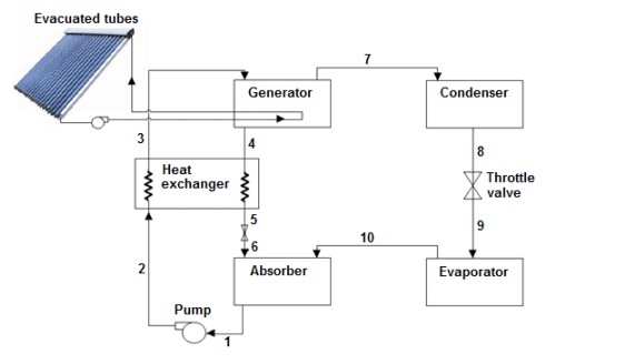
Figure 6: Vapor Absorption Cycle
Condenser:
The type, as well as the temperature of the condensing material, defines the pressure that is to be maintained in the condenser to change the phase of the ammonia vapors. For this purpose, we are using water as a condensing material because it is readily available and has a condensing temperature of 25oC. The value of pressure corresponding to this temperature is found to be Pc = 10 bar from the R-717 table[6].
Evaporator:
The minimum temperature that is to be maintained in the room i.e. office defines the value of pressure for the evaporator in this case. Also, another major point is that pressure in the evaporator should be close to atmospheric pressure. For this purpose, the pressure in the evaporator is defined to be 1 bar and the corresponding value of saturation temperature becomes -33oC[6].
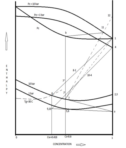
Figure 7: Enthalpy-Concentration Chart
Drawing points 1, 2, 3, and 4 on the enthalpy-concentration chart, the above plot is obtained. Here point 1, 2, 3, and 4 are NH3 saturated vapors at condenser pressure Pc and concentration C = 1, NH3 saturated liquid at condenser pressure Pc and concentration C = 1, pure NH3 at Pe and C = 1 and NH3 at pressure Pe respectively. The values of enthalpies obtained corresponding to these points i.e. 1, 2, 3 and 4 are h1 = 1630 KJ/Kg, h2 = h3 = 460 KJ/Kg and h4 = 1530 KJ/Kg respectively[6].
For the refrigeration capacity which is 1.87 Tons in this case, the refrigeration effect required to be produced is calculated as:
Qe = h4-h3 [6]
Qe = 1530 - 460 KJ/Kg
Qe = 1070 KJ/Kg
The mass flow rate of the NH3 is found by:
Mr = Ton / (h4-h3) [6]
Mr = 5.4559 / 1070
Mr = 1.0708 Kg/min
It can be seen that the water going into the generator is about 800oC, so choosing the value of generator temperature Tg to be 800oC. Now using this temperature as well as the pressure of 1o bar, we find point 8 on the figure and it represents the hot weak liquid having concentration Cw. the value found in this case is 0.418 which shows that it is a weak solution. Point 5 corresponded to the strong aqua which is coming out of the absorber. The value of C5 which is the concentration of strong aqua is found from the following analysis.
C5 = Cw + 0.18 [6]
C5 = 0.418 + 0.18
C5 = 0.596
C5 = 0.6 (assuming)
The value of pressure at this point is found to be 10 bar. Point 6 corresponds to C5 = 0.6 but the pressure of Pc as compared to Pe. Point 7 has more enthalpy as compared to point 6 but the concentration of the solution remains the same so as the pressure. Joining points 7 and 8 and extending to y-axis we get to point 9 and 10. Point 9 has lower enthalpy but still the same concentration and point 10 has the same enthalpy as point 9 but the pressure is reduced to Pe.
Absorber:
In absorber to liquids enter one at a condition 10 and other at condition 4 which are the weak aqua solution and NH3 gas respectively. As a result, a resulting aqua solution at conditions 5 comes out with the loss of heat[6].
Generator:
The purpose of the generator is to heat the strong aqua solution using Qg. The strong aqua solution at condition 7 enters and split into the weak aqua solution at conditions 8 and pure NH3 at condition 1. The two phases move in opposite directions[6].
Calculations:
The amount of heat removed in the evaporator is calculated as:
Heat Removed = Refrigeration Effect
8.415 × 210 TR = Mr × (h4-h3) [6]
The cold water flow rate is Mw and
Mw × cp × = 210 × 5.4559 KJ/min
For = 17oC
Mw = 16.046 kg/min
The amount of heat removed in condenser is given by:
Qc = h4-h3 per kg of NH3 [6]
Qc = Mr × (h2-h1)
Qc = 1.0708 × (1630-460)
Qc = -1252.8 KJ/min
The amount of heat removed from the absorber is given by:
Qa = h4-ha per kg of NH3 [6]
Qa = Mr × (h4-ha)
Qa = 1.0708 × (1550-70)
Qa = 1563.3 KJ/min
Temperature at point 7 is found to be T7 = 82oC. Now,
Mw × Cp × (Ti – T0) = 1563.3 [6]
Mw × 4.18 × (82 - 25) = 1563.3
Mw = 16.046 Kg/min
This is the value of mass flow rate required in the absorber.
Qg is the amount of heat supplied in the generator and Qd is the amount of heat removed from the water, so the net amount of heat removed per kg is given by:
qg – qd = (h7’ – h7) [6]
Then Qd is given by the following equation:
Qd = (h12 – h1) per kg of ammonia [6]
Qd = 1.0708 × (1760 - 630)
Qd = 139.2019 KJ/min
The value of Qg is:
Qg - Qd = (h1 – ha) [6]
Qg = 139.2019 + 1.0708 × (1630 - 70)
Qg = 1809.6 KJ/min
The useful energy for the collector plate is given by the following formula:
Qu = K × S × A [6]
Where,
K = efficiency of collector plate (assume k=0.85)
S = average solar heat falling on earth’s surface = 6 kW hr./m2/day = 250 W/m2
A = Area of collector plates
To convert the heat required in the generator following calculations are made:
Qg = 1809.6 KJ/min
Qg = 1809.6 × 1000/60 J/s
Qg = 30160 J/s
The area of the collector plate is found to be:
A = 30160 / (250 × 0.85)
A = 141.9314 sq. m
So the value of Qu comes out to be:
Qu = 0.85 × 250 × 48.64
Qu = 30160 J/s
The amount of energy stored in the collector plate is U and is given by the following expression:
U = m × Cp × (To – Ti)
U = 0.1088 × 4200 × (82-25)
U = 26046.72
COP:
The COP of the given system consists of two parts, one is related to the refrigeration unit and the other one is related to the whole system and is found by the following formula [6]:
COPR =
COPR =
COPR = 0.6331
And
COP =
COP = 0.5382
Results:
The major point of this whole analysis are:
- Mass flow rate of cold water = 75 Kg/min
- Condenser pressure = 10 bar
- Evaporator pressure = 1 bar
- Heat input required (at generator) = 6 KJ/min
- Area of the solar collectors required = 93 m2
- Output temp of water from solar heater = 84oC
- COP of refrigerating unit = 0.6331
- COP of the whole system = 0.5381
Comparison of cost of VAS with VCC:
In general, a VAS has more cost in comparison to VCC which is because VAS has additional components like absorber and generator. Also, the maintenance cost of VAS is higher compared to VCC. For 5.6 ton of air conditioning requirement following systems were selected.
O-General Duct Able Air Conditioner having a Capacity of about 5.6-Ton of refrigeration. The general features of this air conditioner are given below:
Table 1:
|
Capacity |
5.4-Ton |
|
Usage |
Office Use |
|
Brand |
O-General |
|
Type |
Ductable Air Conditioner |
|
Operating Voltage |
220V 420V |
|
Material |
Aluminum |
|
Power |
Electric |
|
Moisture Removal |
2 L/hr |
|
Input power |
220-240/1/50 V/Hz |
|
Running Current |
9.5 A |
|
Model No. |
ARG18A |
|
Capacity |
5.6-Ton [7] |
The design features of the unit are as follows:
Table 2:
|
Room Air Circulation (High) - Indoor |
1100 33/hr |
|
Power Consumption |
2.1 Kw |
|
EER |
2.57 Kw |
|
Refrigerant Type |
R-22 |
|
Dimension HxWxD - Indoor |
217 x 953 x 595 mm |
|
Dimension HxWxD - Outdoor |
643 x 840 x 336 mm |
|
Connection Method |
Flare |
|
Connection Pipe Size (Small/Large) |
9.52/15.88 mm |
|
Max Pipe Length |
25 m |
|
Height Difference |
15 m |
|
Operating Temperature |
52 Degree c [7] |
The cost comparison of VAS and VCC is given below:
|
Parameter |
VCC |
VAS |
|
Initial Cost |
$2000 - $5000 |
$3000 - $7000 |
|
Maintenance Cost |
Requires a lot of maintenance $500- $1000 |
Moderate amount of maintenance required $200 - $400 |
|
Operational Cost |
$6000 - $10000 |
$4000 - $8000 |
|
Vibrational or Sound Effects |
Noisy and Vibrational |
Quiet and non-vibrational |
|
Energy Source |
Electrical power |
Solar energy |
|
Payback Period |
2 – 2.5 years |
1 – 1.75 years |
Environmental Impact and sustainability of VAS against VCC:
As the world is progressing they are trying to make the best refrigerant to meet the needs of the refrigeration systems. Effective and environmentally friendly refrigerants are being used to make the world a better living place and to ensure a green society. That’s why they have banned the usage of the R134a to use in the systems. The VCS systems used safe refrigerants in the working. The ammonia or lithium bromide with water if the refrigerant is used in the VAS system. This system is considered as harmless as far as concern for refrigerant usage. it does not release any of the harmful gases while working. But in comparison, the VCS system the refrigerant that is used is the cause of the CFCs and HCFC. These gases are released in the environment and then they go to the ozone layer. This is the source of environmental destruction. The ultraviolet rays enter the atmosphere then they cause the skin cancerous effects on the living beings. According to the report from 2015 to 2019, the fall of the UV rays has been significantly increasing and is causing cancer to people. So indirectly the refrigerant is harming the human being itself. Also, they are the sources of global warming. The climatic change is the major concern of the world today. Most of the people die every day due to the climatic change effects like floods droughts typhoons etc. than any other disease. So the scientist is trying their best to find the effective and best replacement of the refrigerant that are the source of CFCs. But still, these VCS systems are widely used so this causing society a disturbing impact.
Secondly, the usage of both systems varies in a wide range. The VCS systems are effectively used on the high-grade energy that is being produced by fossil fuel. So air pollutions and greenhouse gases are the main concern for using the VCS. But in the case of the VAS, low-grade energy is required. Even solar energy can be used. Also, the waste material can drive the VAS system. So the VAS system is better than VCS in terms of the refrigerant and the energy source usage.
Conclusion:
A comprehensive analysis was performed on an office for the weather conditions of Karachi, Pakistan. The basic idea of applying passive techniques was to reduce the cooling loads to about 50%. The major reason is the reduction of the cooling loads was the usage of insulating material and the orientations of that building. It is found from the analysis that before the application of passive techniques in the design of the building the cooling and heating loads of the building were relatively high i.e. 29041624 Watts and were reduced to about 13467170 Watts. This is a reduction of about 53% in the cooling and heating loads. Based on these cooling and heating the maximum value for the cooling load was about 19183 W i.e. 5. 4559 tons at 16:00 on 29th August. Based on this cooling load a vapor absorption cycle was designed to have COPR of 0.6331 and COP of 0.5382. The mass flow rate of the refrigerant was designed to be 24.75 Kg/min with the pressure of condenser and evaporate to be 10 bar and 1 bar respectively and the heat input requirement of the generator was designed to be 1809.6 KJ/min. The comparison of cost i.e. capital, maintenance, and operational cost of VAS and VCC was also made and it was found that VCC is more reliable in comparison with VAS in the matter of capital cost. In the end, it was found that the VAS is more environmentally friendly and produce less pollution as compared to VCC. The emissions of VCC which are CFCs and HCFCs are much more dangerous for the environment i.e. it affects the ozone layer of the atmosphere. Therefore, VAS is more suitable due to its less harmful effect on the environment.
References:
- Andersson, B., et al., The impact of building orientation on residential heating and cooling. Energy and buildings, 1985. 8(3): p. 205-224.
- Kossecka, E. and J. Kosny, Influence of insulation configuration on heating and cooling loads in a continuously used building. Energy and Buildings, 2002. 34(4): p. 321-331.
- Bokel, R. The effect of window position and window size on the energy demand for heating, cooling and electric lighting. in Building Simulation. 2007.
- Stegou-Sagia, A., et al., The impact of glazing on energy consumption and comfort. Energy Conversion and Management, 2007. 48(11): p. 2844-2852.
- Venkiteswaran, V.K., J. Liman, and S.A. Alkaff, Comparative Assignment of Passive Methods for Reducing Cooling Load. Energy Procedia, 2017. 142: p. 2689-2697.
- Bajpai, V. Design of solar powered vapour absorption system. in Proceedings of the World Congress on Engineering. 2012.
- indiamart.com. Air Conditioner Unit prices. 2020 [cited 2020; Available from: https://www.indiamart.com/proddetail/ductable-air-conditioner-15521387488.html.


