UML Sequence Diagrams Assignment Help
Sequence diagrams represent the interactions among classes in terms of an exchange of messages over time. We are here to help you in your Assignment related to UML Sequence Diagram.
A sequence diagram shows, as parallel vertical lines (lifelines), different processes or objects that live simultaneously, and, as horizontal arrows, the messages exchanged between them, in the order in which they occur. This allows the specification of simple runtime scenarios in a graphical manner. A sequence diagram is made up of objects and messages. Objects are represented exactly how they have been represented in all UML diagrams—as rectangles with the underlined class name within the rectangle.
Basic Sequence Diagram symbols and notations:

Class Role: Class roles describe the way an object will behave in context. Use the UML object symbol to illustrate class roles, but don't list object attributes.

Sequence Diagram Class Role Diagram
Activation: Activation boxes represent the time an object needs to complete a task.
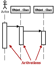
Sequence Diagram Activation Diagram
Messages: Messages are arrows that represent communication between objects. Use half-arrowed lines to represent asynchronous messages.
Asynchronous messages are sent from an object that will not wait for a response from the receiver before continuing its tasks.
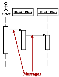
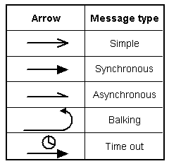
Sequence Diagram Messages Diagram
Lifelines: Lifelines are vertical dashed lines that indicate the object's presence over time.
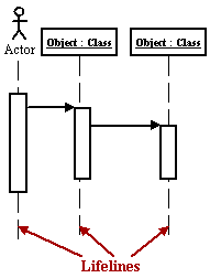
Sequence Diagram Lifelines Diagram
Destroying Objects: Objects can be terminated early using an arrow labeled '<< destroy >>' that points to an X.
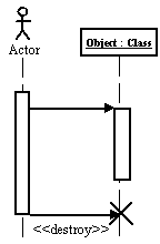
Sequence Diagram Destroying Objects Diagram
Loops: A repetition or loop within a sequence diagram is depicted as a rectangle. Place the condition for exiting the loop at the bottom left corner in square brackets [ ].
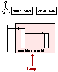
Sequence Diagram Loop Diagram

To submit UML assignments Click here


