Analysis and Design Tools Assignment Help
Analysis and Design Tools: Analysis Definition and Flow Charts Introduction
Introduction to analysis and design
Generally, we define analysis is broken down something into interrelated components to understand it. We can also define analysis like a program that run automatically to analysing the behaviour of the program to satisfy some of the properties such as correctness, robustness, safety and liveness. The Analysis focuses on improving the performance when the less usage of resources. Analysis objects can be raw data, it can be a business process, or learning how to program. An analysis of software includes all those activities that help it to transform the requirement specification into implementation of the software. As requirement specification emphasis of all functional and non-functional expectation of the software and they all are in human readable documents of which computer has nothing to do. Analysis and design is one of the intermediate stage while making any software that help the programmer which turn human readable document into actual code to run software as per specifications.
Flow charts
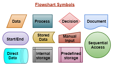
This is one of the formalized process that represent graphically the work flow, manufacturing process and organization of the chart of the formalized structure. The main purpose of the flow chart is to provide people with a common language that deal with the process or project. Flowcharts contain geometric symbols and arrows that define relationship among entities. This provide a step-by-step process for mapping the complex situations that com while writing program. Let’s take an example of flowcharts in programming where any instance that comes in beginning and end represented by oval. Now we are going to discuss flowchart symbols and how they are going to use while making flowchart.
Analysis and Design Tools Assignment Help By Online Tutoring and Guided Sessions at AssignmentHelp.Net
Learn from our expert tutors how to make flowchart to easily proceed in you project by making flowchart of each module on every step. Click here to submit your requirement.
Flowchart symbols
- Data object: Data object often referred for the Input and Outputs from a process.
- Rectangle: rectangle is used to represent event control within the process which is a step or action that is going to take.
- Diamond: this is used to represent a decision point in the process that contain two conditions either yes or no, so to direct different part of the flowchart accordingly.
- Document: this symbol is used to represent a document in the process flow it is like a rectangle with the wave-like base.
- Rounded Box: rounded box is an event that occur automatically, this event is triggered only when a subsequent action is to be performed like to receive telephone and so on.
- Stored Data: this object is used to store data as the name implies in the process flow. The data which could be stored on a hard drive, magnetic tape, of any other storage device.
- Manual Input: this object determine an action where user is promoted for information that must be manually input into a system. Manual input is represented by rectangle with the top sloping up from left to right.
- Direct Data: this data object in the process flow that represent stored information which can be accessed directly and this object represents a computer’s hard drive.
- Circle: this symbol is used to represent that one processes connect to another one and the name of the process should appear within symbol.
- Internal Storage: the object is commonly found in programming flowcharts to depict the information stored in memory.
- Predefined Process: this object allows to write one subroutine and call it whenever needed in the code.


