UML Component Diagrams | UML Homework Help
UML Component Diagrams
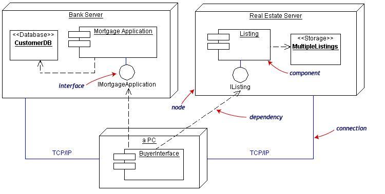
A component is a code module. Component diagrams are physical analogs of class diagram. Deployment diagrams show the physical configurations of software and hardware. Figure shows the relationships among software and hardware components involved in real estate transactions.
The figure given below shows how to send message in Collaboration Diagram
Component diagrams describe the organization of physical software components, including source code, run-time (binary) code, and executables.Components are wired together by using an assembly connector to connect the required interface of one component with the provided interface of another component. A component diagram describes the organization of the physical components in a system.
The figure given below shows how to send message in Collaboration Diagram
Basic Component Diagram symbols and notations:
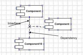
Component: A component is a physical building block of the system. It is represented as a rectangle with tabs.

Interface: An interface describes a group of operations used or created by components.

Basic Deployment Diagram Symbols and Notations

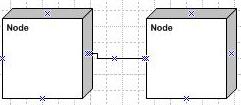
Node: A node is a physical resource that executes code components.

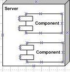
Components and Nodes: Place components inside the node that deploys them.

To submit UML assignments Click here


