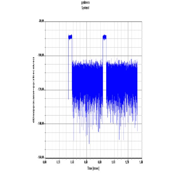
Transmit Waveform Power Of Digital Pulse Radar

Assignmenthelp.net is a premium global learning platform in providing matlab assignment help, support resistance matlab finance, simple matlab projects, project matlab code, phd projects in matlab and online Statistics tutor matlab.

Transmitted Waveform Output Typical Characterstics:
a) Pulse modulated.
b) Time dependent
c) Narrow bandwidth
d) Follows Inquest theorem
Antenna Physical Characteristics:
Radio signals broadcast a reasonable amount of power on the "target", the transmitting aerial should also be directional.
Parabolic DPR:
DPR systems uses a steerable parabolic "dish" to create a tight broadcast beam, typically using the same dish as the receiver. Such systems often combine two radar frequencies in the same antenna in order to allow automatic steering, or radar lock. Symmetric parabolic antennas produce a narrow "pencil" beam in both the X and Y dimensions and consequently have a higher gain. The Digital Pulse Radar weather radar uses a symmetric antenna to perform detailed volumetric scans of the atmosphere.
Types of scan by DPR
Primary Scan: A scanning technique where the main antenna aerial is moved to produce a scanning beam, sector scan.
The typical size of such antenna is 2.8m diameter to 7.1 meter diameter.
System Requirements
Taking all of the above characteristics into account means that certain constraints are placed on the radar designer. A system with a 25 MHz carrier frequency and a pulse width of 1us will have a carrier period of approximately 333ps. Each transmitted pulse will contain about 2852 carrier cycles and the velocity and range ambiguity values for such a system would be:
| PRF | Velocity Ambiguity | Range Ambiguity |
| Low (24MHz) | 28 m/s | 62 km |
| Medium (30MHz) | 163 m/s | 8 km |
| High (49Mhz) | 2852m/s | 789m |
Some sea clutter is expected to be faced by the design of the antenna system.
Radar Cross Section of DPR:
The radar cross section (RCS) of a target is a measure of a targets reflectivity in a given direction. The main contributors to RCS are:
Specular scattering localized scattering dependent on the surface material/texture
Diffraction scattering incident signal scattering at target edges and discontinuities
Multiple bounce reflections among target elements at offset angles
The objective in modelling RCS is to develop simulation tools capable of predicting the behaviour of radar receivers in a realistic environment.
Orientation: Movable at 42 degree from the sea surface.
Range Equation:
The power Pr returning to the receiving antenna is given by the radar equation:

where
Pt = transmitter power
Gt = gain of the transmitting antenna
Ar = effective aperture (area) of the receiving antenna
s = radar cross section, or scattering coefficient, of the target
F = pattern propagation factor
Rt = distance from the transmitter to the target
Rr = distance from the target to the receiver.
In the common case where the transmitter and the receiver are at the same location, Rt = Rr and the term Rt Rr can be replaced by R4, where R is the range. This yields:
This shows that the received power declines as the fourth power of the range, which means that the reflected power from distant targets is very, very small.
The equation above with F = 1 is a simplification for vacuum without interference. The propagation factor accounts for the effects of multipath and shadowing and depends on the details of the environment. In a real-world situation, path loss effects should also be considered.
MATLAB Assignment Help | Programming Assignment Help | MATLAB Programming Help | Online Tutoring


