Quartus FPGA Design Help And HDL Hardware Description Language

Quartus FPGA Design Help And HDL (Hardware Description Language) Assignment Help
Our expert assisting students with Matlab homework online tutors provide engineering project on matlab in the following areas of online computer programming help matlab, various project on matlab in logistics, wacc matlab,tyre centripetal force model matlab,simple harmonic motion derivatives matlab7c, optical young s fringe matlab and related Question as follows:
FAQ:
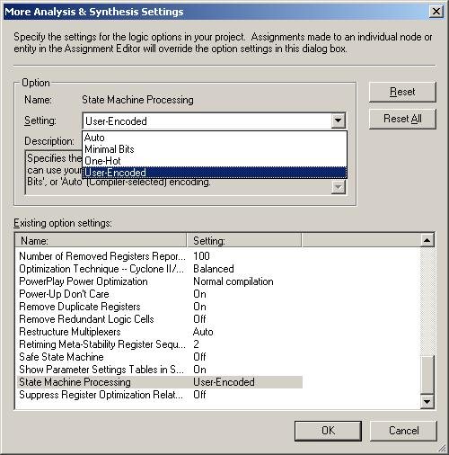
Q How do I stop Quartus from overriding my state assignment and using more flip-flops ('registers' in Quartus)?
A: Go to menu Assignments ->Settings->Analysis and Synthesis Settings->More Settings->State Machine processing and change to User-Encoded. See the following dialogue box:

Q
It asks for using 5 flip flops. So, do we have to implement Moore FSM by using only combinational logics, or we could use 'case' instructions ?
A:
1 A FSM cannot be implemented with just combinational logic since it is a sequential circuit. However if you separate out the state flip-flops, the remaining logic can be combinational. The state flip-flops can be created from an always block - using instantiation of separate flip-flops is not necessary.
2. Case statements can result in combinational or sequential logic on synthesis, depending on how they are used. A combinational circuit results from all input combinations being covered in the always block and no posedge conditions in the sensitivity list of the always block. Here is an example if a combinational use of a case statement :
module hexdisplay(binary, hex);
input [3:0] binary;
output reg [6:0] hex;
always @(binary)
case (binary)
0: hex <= 7'b 1000000;
1: hex <= 7'b 1111001;
2: hex <= 7'b 0100100;
3: hex <= 7'b 0110000;
4: hex <= 7'b 0011001;
5: hex <= 7'b 0010010;
6: hex <= 7'b 0000010;
7: hex <= 7'b 1111000;
8: hex <= 7'b 0000000;
9: hex <= 7'b 0011000;
default: hex <= 7'b 1111111;
endcase
endmodule
Here is an example of a sequential circuit from a case statement with 3 flip-flops inferred
module string_recog_FSM(Clk, X, reset, Z);
output Z;
input Clk, X, reset;
reg state[0:2];
parameter S0 = 3'b000; // reset state
parameter S1 = 3'b001; // strings ending in ...0
parameter S2 = 3'b010; // strings ending in ...01
parameter S3 = 3'b011; // strings ending in ...010
parameter S4 = 3'b100; // strings ending in ...1
parameter S5 = 3'b101; // strings ending in ...10
parameter S6 = 3'b110; // strings ending in ...100
assign Z = (state == S3);
always @(posedge Clk)
if (Reset) state = S0;
else case(state)
S0: if (X) state = S4 else state = S1;
S1: if (X) state = S2 else state = S1;
S2: if (X) state = S4 else state = S3;
S3: if (X) state = S2 else state = S6;
S4: if (X) state = S4 else state = S5;
S5: if (X) state = S2 else state = S6;
S6: state = S6;
default: state = 3�bxxx;
endcase
endmodule
Q: How should I display the signals in the simulations particularly the 7 segment display outputs.
A: I suggest you use a module with sensible signal names and then display the 4 bit output before the seven segment display in decimal (right click on the signal in the wavefile and change the radix to unsigned decimal) and the seven segment as a 7 bit binary output (rather than each individual bit).
Q: Draw the state diagram for the FSM. Are we supposed to draw the diagram using Quartus II or hand drawn? Is there any effect on the marks if we decide to draw the state diagram by hand?
A: As long as the diagram is readable, not in pencil and has a key then hand drawn diagrams are as good as any more time consuming electronic drawing package. I prefer students to put time into understanding and solving the problem rather than prettying up diagrams electronically.
Q: How will the Digital Systems assignment will be marked?
A: Q1.1 and Q3.1 2 marks, all other parts are worth 1 mark each, giving a total of 10 marks.
Q: Does our code require commenting?
A: Yes each module should be commented with a few lines defining functionality, inputs and outputs. Short comments in the body of the code are also expected, but not if they do not add to the meaning - that is do not repeat the obvious that is clear from the Verilog code itself.
Q: How much logic minimisation (i.e. through state assignment) is required?
A: None - the Quartus compiler will do output logic minimisation for you and I do not expect any minimisation from the state assignment.
Q: If the compilation summary report says the project contains 5 registers, does that actually mean it contains 5 flip-flops?
A: Yes. You should also check the RTL netlist viewer (see menu Tools-> netlist viewers -> RTL viewer) for the synthesised hardware from Quartus.
MATLAB Assignment Help | Programming Assignment Help | Online Tutoring


