Primary Reformer Mechanical Design Assignment Help
In this section a mechanical design for the primary reformer tubes inside the furnace will be carried out. From the chemical design section we assumed each tube is 9 m long and has an internal diameter of 0.12 m.

§ Design Pressure:
The pressure inside the vessels is 30 bar. 10% above operating pressure was considered for safety:
= (30-1) x 1.1
=31.9
=32 bar
= 3.19 N/mm2
§ Design Temperature:
Design temperature = 800oC (1073 K.)
§ Thickness of tube:
The minimum thickness required to resist internal pressure is :

Primary Reformer Mechanical Design Assignment Help By Online Tutoring and Guided Sessions from AssignmentHelp.Net
e = the minimum thickness required.(mm)
Pi= Internal pressure. (kN/mm2)
Di=Internal diameter. (mm)
f= Design stress factor.
e = (120x3.19)/((2x115)-3.19)
e= 1.7 mm
We add 1mm for corrosion e= 1.7+1 =2.7 mm.
§ Heads and closures:
The 2 ends of each tube are designed to be closed by a head. There are three types of heads:
1. Hemispherical heads.
2. Ellipsoidal heads.
3. Torispherical heads.
Ø For a standard Torispherical head:
§ Crown radius Rc = Di = 0.12m.
§ Knuckle radius= 6% of Rk =7.2x10⁻³m.
§ A head of this size would be formed by pressing no sides, therefore j= 1.

Cs = Stress concentration factor for Torispherical heads.
Cs = ¼ (3 + ((0.12/7.2-3))-1/2)
Cs= 1.77

e = (3.2 x 120 x 1.77)/ ((2x115) + 3.2 (1.77-0.2))
Thickness of head e = 2.9 mm.
Ø For a standard ellipsoidal head:
 Most standard ellipsoidal heads are manufactured with a major and minor axis ratio of 2:1
e =(3.2x 120)/ ((2x115)- (0.2x3.2)
e = 1.7 mm =2.77mm (1 mm corrosion allowance)
Ellipsoidal head would probably be the most economical choice as it needs approximately half the thickness of a torisphrical head.
n Calculation of reinforcement required:
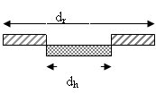
The presence of an opening weakens the shell and gives rise to stress concentration around the openings. To compensate the effect of an opening the thickness is increased in the area adjacent to the openings. There are two openings in each tube, one for the feed at the top and the other for the exiting product at the bottom (fig 4.13)

A welded pad will be used:
dh = 0.03 m
dr = 2 x dh
= 2x 0.03 = 0.06m
dh = diameter of hole (opening) m
dr = diameter of pad + opening adjacent surface.
( A factor of 1.5 to 2 is usually used in this equation)
n Design of loadings:
Primary Stress:
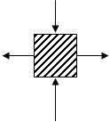
There are three types of stress due to the internal pressure.
- Horizontal (circumferential) stress:

Stress h = (3.2x120) /(2x2.7)
= 71.11 N/mm2
P= Internal pressure. N/mm2
Di= Internal diameter.(mm)
t = shell (tube) thickness. (mm)
- Longitudinal stress:

Stress L = (3.2x120) / (4x2.7)
= 35.5 N/mm2
P= Internal pressure. N/mm2
Di= Internal diameter.(mm)
t = shell (tube) thickness. (mm)
- Compressive stress:
For stainless steel E= 200,000 N/mm2

Stress C = 2x104 x(2.7/122.7)
= 440 N/mm2
Stress C= critical bulking stress
t = thickness
Do = outside diameter.
The maximum compressive stress should not exceed 440 N/mm2 in the vessel or the vessel may fail by elastic instability.
- Weight Loads:
The major sources of dead weight loads are:
Ø The vessel shell.
Ø The vessel filling ( e.g. nozzles).
Ø Internal fittings.
Ø External fittings.
Ø Insulations.
Wv = 240 x Cv x Dm (Hv + 0.8 Dm) t
Wv = Total weight of shell, excluding internal fittings.
Cv = a factor to account for the weight of nozzles, internal supports...etc.
( a factor of 1.08 is used with only few internal fittings)
Hv = length of cylindrical section.(m)
Dm= mean diameter of vessel ( Di + t) in (m).
t= shell thickness (mm).
Wv = 240 x 1.08 x 0.1277 (9 + 0.8 x 0.1227 ) x 2.7
= 813 N
- Earthquake loading:
Sites in the United Kingdom do not carry out seismic stress analysis in preliminary design of vessels. Since this mechanical design is for a plant in the U.K the seismic stress analysis will neglected. (page 837)
Fs = ae (w/g)
g=the acceleration due to gravity.
ae=the acceleration of the vessel due to earthquake.
W= the weight of the vessel.
- Dead weight of the vessel.
W= Wv ( = 781 kN) + catalyst weight
Catalyst used= Nickel
Density = 43.5kg.m3
Mass = 43.5x 0.407 = 17.7m3
Weight = mass x g
= 173.5 N
Dead weight = 1044.5N
- Wind Loading:
Fw = wind pressure x Main diameter
Fw = 1280 N/mm2 x 0.12
Fw = 153.6 N/m
- Bending moment:
Mx =(Fw/Di) x L2
Mx = (153.6 / 0.12) x 92
Mx = 103680 N/m
§ Analysis Stress:
Ø Pressure Stress
Stress σ L = 35.5 N/mm2
Stress σ h = 71. N/mm2
Ø Dead Weight stress
Stress σ w = Wv /( 3.14 x (Di +t) x t
Stress w = 1044.5 x (3.14 x (120 + 2.7 ) 2.7
Stress w = 1.0 N/mm2 (compressive)
Ø Bending stress:
Do = 122.7 mm (outside diameter)
Iv = (3.14/ 64) x ( Do4 – Di4 )
Iv = the second moment of area of the vessel about the plane of bending.
Iv = (3.14 / 64) x ( 122.7x10⁴ - 120x104)
Iv = 9.4x10⁵
Stress σ b = +/- (M/Iv) x ((Di/2)+t)
Bending stress=
Bending stress=+/- (103680 /9.4x105) x ((120/2)+ 2.7)
Bending stress= 69.15 N/mm2
σ
Ø The resultant longitudinal stress:
Stress σ z = stress l + stress w +/- stress b
(Stress σ w is compressive therefore –ve)
Stress σ z = 35.5 – 1 + 69.15 = 33.65 N/mm2
Stress σ z = 35.5 - 1 - 69.15 = -34.65 N/mm2


The great difference between the principal stresses will be on the down wind side:
(71.1 – (-34.6)) = 107.5 N/mm2
The vessel will stand the internal stress since the difference between the principal stresses is below the design stress.
Support:
§ type of support: Bracket support (Single plate)
1) for the back row tubes :
Fbs = 60 x 150 x 20 =18x 104 N
2)For the front row tubes:
Fbs = 60 x 250 x20 = 30x104 N
L= length of bracket support (mm)
T = thickness of support (mm)
Reference:
Chemical Engineering design, Coulson and Richardson, vol.6, 3rd Edition, section 13.
Vessel Data Sheet
Description (Furnace):Primary Reformer
Type of vessel
Reactor Tubes
No of tubes Required:
614
Capacity
0.105 m3
Contents
Methane and Steam
Premixed
Catalyst
Nickel catalyst
Density
53.5 kg/m3
Diameter
0.12
m
Length
m
Max working Pressure
38
bar
Design Pressure
bar
Max working Temperature
1200
K
Design Temperature
1073
K
Estimation of Temp inducing creep
1315
oC
Materials
Stainless Steel 314
Joint Factor
0.70
Corrosion Allowance
1 mm
Thickness
2.7 mm
End Type
Ellipsoidal head
Thickness
2.9 mm
Joint Factor
0.70
End Type
Ellipsoidal head
Thickness
2.9 mm
Joint Factor
0.70
Type of support
Brackets
Thickness
20 mm
Material
Steel
Wind Load Design
6.65 kN/m
Radiography
None
Dead Weight
1044 N
Weight of catalyst
170 N
Bending Stress
15.7 N/mm2
Dead weight Stress
0.42 N/mm2
Max design load of bracket support
372 k/N
Project title: Synthesis of Ammonia from Natural Gas
Company : Zeta Process Engineering
Designed By:
Course: Beng Chemical Engineering
Talal Omar
Project: Design Project
Supervisor
Dr S.Larkai
London South Bank University
Approved:
Dr R.Best
Assignment Help | Mechanical Engineering Assignment Help | Mechanical Engineering Homework Help | Online Tutoring


