Norton Theorem Assignment Help
www.assignmenthelp.net is an online tutoring website designed to provide tutoring help to school and college level students. Submit Your Courseworks to us, we provide 100% plagiarism free service. Assignmenthelp.net provides norton’s theorem Assignment Help, electrical engineering Assignment Help or electrical engineering homework help. Contact us anytime of the day, we are available 24*7.
Norton theorem Tutor
We have highly professional tutors and an excellent team for teaching Norton theorem and its problems. Tutors for this topic are electrical engineers with masters and PHD degrees. They use latest advanced technologies to teach different difficult concepts to students. Tutors use such teaching methodologies so that students gain maximum interest in the subject.

Norton theorem
Norton theorem states that: any linear network with current sources, voltage sources and only resistances can be replaced at terminals A-B by an equivalent resistance RNO in parallel combination with an equivalent current source INO. The equivalent current INO is the current obtained at A-B terminal of the network when A-B terminal is short-circuited. The equivalent resistance RNO is the resistance obtained at terminals A-B of the network with all its current sources open circuited and all its voltage sources short circuited. For AC systems the theorem can be applied to resistances as well as reactive impedances. Norton equivalent circuit is used to represent any network of linear sources and impedances at a given frequency.

Fig(1): Norton Equivalent Circuit
To find the Norton equivalent we have to find the Norton current INo. To calculate INo we have to calculate IAB with short circuit as the load, which means zero resistance between A and B. This current is INo. Now we have to find the Norton resistance RNo. There are two methods of determining the Norton impedance RNo when there are no dependent sources. The first method is: calculate the output voltage VAB in open circuit condition. Here RNo equals VAB divided by INo. The second method is: replace the independent current sources with open circuits and independent voltage sources with short circuit. The total resistance across the output port is the Norton impedance RNo.
Norton theorem Example
Norton theorem says that it is possible to simplify and linear complex circuit to an equivalent circuit with a single current source and parallel resistance connected to the load. Let us take a look at our example circuit:
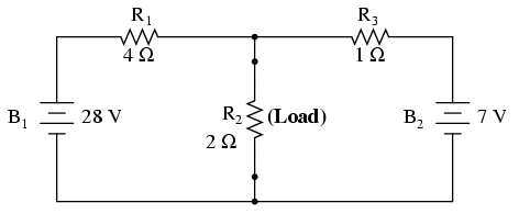
. . . after Norton conversion . . .
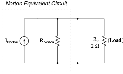
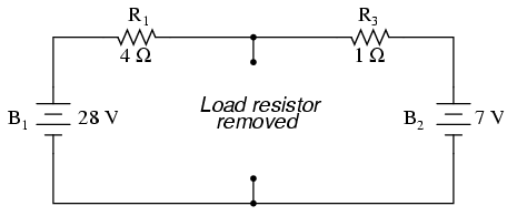
Always remember that a current source’s job is to provide constant current while outputting as little voltage necessary to maintain that constant current. Everything except the load has to be changed to an equivalent circuit which is simpler to analyze just like we did in thevenin theorem’s example. Here we need to calculate Norton source current (INorton) and Norton resistance (RNorton). The first step is to identify the load resistance and remove it from the original circuit
Now place a direct wire (short connection) between the load points to determine the Norton current (for the current source in the Norton equivalent circuit):
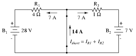
There is zero voltage drop between load resistor connection points hence the current through R1 is a function of B1’s voltage and R1’s resistance: 7 amps (I=E/R). Similarily, I through R3 is a function of B2’s voltage and R3’s resistance: 7 amps (I=E/R). The total current through the short is the sum of these two currents: 7 amps + 7 amps = 14 amps. Hence now 14 amps is the Norton source current (INorton) in the equivalent circuit.
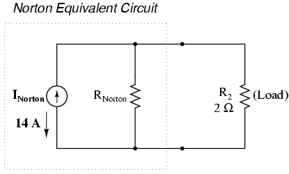
Now, to calculate the Norton resistance (RNorton), we take the original circuit (with the load resistor still removed), remove the power sources, replace voltage sources with wires and current sources with breaks and then figure total resistance from one load connection point to the other:
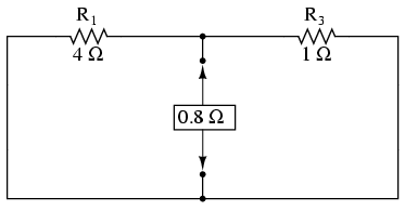
Now our Norton equivalent circuit looks like this:
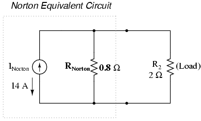
If we connect the original load of 2 Ω, now it is a simple parallel arrangement of 2 resistors:
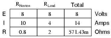
The only useful information from this analysis is the current and voltage values for R2, rest of the information is irrelevant to the original circuit. If we want to know load resistor current and voltage over different values of load resistance, we can use the Norton equivalent circuit for each value, which is a simple parallel circuit analysis.
Norton Theorem |Norton Theorem Assignment Help | Electrical engineering homework help | Electrical engineering Assignment Help| Electrical engineering project help | help with Electrical Engineering Courses.


