Design Of A Lead Controller Using Root Locus Assignment Help

Design Of A Lead Controller Using Root Locus:
In root locus form, a lead compensator is given by
G(s)=Kc (s-zo) /(s-po)
|zo | < |po|. A phase-lead compensator tends to shift the root locus toward the left half plane. So we have more stability and an increase in the response speed.
matlab complex root z5e31
The equation to determine the intersection of the asymptotes along the real axis is:
a= (sum of poles - sum of zeroes ) / (no. of poles - no of zeroes)
With the inclusion of lead compensator, intersection value will be a larger negative number. Net number of zeroes and poles is same but added pole has more negative value than added zero. So asymptotes will intersect in left hand plane and entire root locus is shifter to the left hand plane Hence we have more stability and good response speed.
Design Of A Lead Controller Using Root Locus Assignment Help Through Online Tutoring and Guided Sessions from AssignmentHelp.Net
The Matlab code fort the design of lead compensator for our system is given as
A = 104;
B = -64;
C = -6656;
K = 520;
num=K;
den=[1 A B C];
open_loopTF=tf(num,den)
%design of a lead compensator in Matlab
%Glead(s) = Kc(s-z0)/(s-p0)
%selecting f=100KHz
T=10e-6;
p=1/T;
Kc=20000;
z=1/(Kc*T);
numlead=[Kc/p 1];
denlead=[1/p 1];
Glead = tf(numlead, denlead)
Gtot=Glead*open_loopTF*H
figure
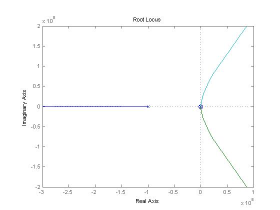
rlocus(Gtot)
matlab complex root z^31
Transfer function of lead controller= (0.2 s + 1)/ (1e-005 s )

Figure: Root Locus with Lead Compensator function added
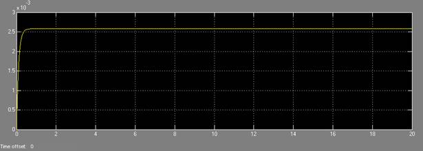
The system response with the gain compensator from the simulink model is taken is and is shown below. Assuming 2.5mm input
Overshoot= (2-5825-2.5)/2.50 =0.033=3.3%

Figure: System response showing overshoot
MATLAB Assignment Help | MATLAB Programming Help | Programming Assignment Help | Online Tutoring


