DC motor Assignment Help
DC motor Assignment Help
www.assignmenthelp.net is an online tutoring website designed to provide tutoring help to school and college level students. Submit Your Courseworks to us, we provide 100% plagiarism free service. Assignmenthelp.net provides DC motor Assignment Help, electrical engineering Assignment Help or electrical engineering homework help. Contact us anytime of the day, we are available 24*7.
DC motor Tutor
We have highly professional tutors and an excellent team for teaching DC motor and its problems. Tutors for this topic are electrical engineers with masters and PHD degrees. They use latest advanced technologies to teach different difficult concepts to students. Tutors use such teaching methodologies so that students gain maximum interest in the subject.

DC motor
A DC motor is powered by direct current (DC current) and is a mechanically commutated electric motor. The current in the rotor is switched by the commutator to be stationary in space because the stator is stationary in space. This is how we are able to maintain the relative angle between stator and the rotor magnetic fields at 90 degrees to generate the maximum torque. DC motors have a static field windings (the windings which produce the magnetic flux) or permanent magnet and rotating armature windings (the windings in which the voltage is induced) but non rotating armature magnetic flux. Different connections of field and armature windings provide different inherent speed/torque regulation characteristics. The speed of a DC motor can be changed by changing the voltage applied to the armature or by changing the field current. If we introduce a variable resistance in the armature circuit or field circuit then we can control the speed of the motor. Modern DC motors are generally controlled by DC drives (power electronics system). The need for local steam or internal combustion engines and line shaft drive systems was eliminated by the introduction of DC motor. Rechargeable batteries can operate DC motors, providing the motive power for the first electric vehicles. Today the DC motors are still found in applications in large sizes like to operate steel rolling mills and paper machines or in applications as small as toys and disk drives.
Operating principle of DC motor
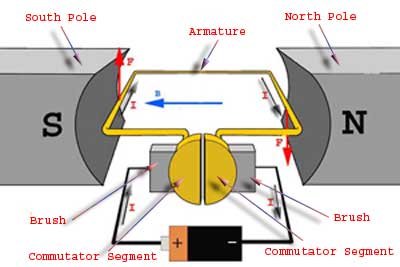
Very simple we can say that a DC motor is a device that converts direct current into mechanical energy. To completely understand the operating principle of dc motor we need to look into the constructional feature of DC motor. Basically, a DC motor contains a current carrying armature which is connected to supply end through the commutator and brushes. The armature is placed within the north-south pole of the permanent magnet or an electromagnet (see the diagram below). To understand the operating principle of dc motor we need to very clearly understand Fleming’s left hand rule which is used to determine the direction of force acting on armature conductors of DC motor.
DC motor Assignment Help Through Online Tutoring and Guided Sessions from AssignmentHelp.Net

Fig (1): DC motor basic construction.
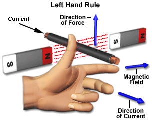
Fleming’s left hand rule says that if we extend the index finger, middle finger and thumb of our left hand in such a way that the current carrying conductor is placed in a magnetic field (represented by the index finger) is perpendicular to the direction of current (represented by the middle finger), then the conductor experiences a force in the direction (represented by the thumb) mutually perpendicular to both the direction of field and the current in the conductor.

Fig (2): Fleming's left hand rule.
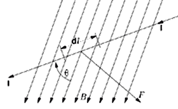
In order to get a clear understanding of the operating principle of DC motor, we need to determine the magnitude of force on the armature windings. (see the diagram below)

Fig (3): Force experienced by a current carrying conductor in a magnetic field.
The Lorentz force dF experienced by the small charge dq which is made to flow with a velocity ‘v’ under the influence of magnetic field ‘B’ and electric field ‘E’ is given by:
dF = dq(E + v X B)
For the operation of dc motor, consider E = 0
dF = dq v X B
i.e. it’s the cross product of magnetic field B and dq v.
or dF = dq (dL/dt) X B [v = dL/dt]
Where dL is the length of the conductor carrying charge q.
or dF = (dq/dt) dL X B
or dF = I dL X B [Since, current I = dq/dt]
or F = IL X B = ILB Sinθ
or F = BIL Sinθ
From the first diagram it is clear that the direction of current through the armature conductor at all instances is perpendicular to the field. Hence a constant force acts on the armature conductor the direction of which is perpendicular to both uniform field and the current.
i.e. θ = 90°
Because the currents in the left hand side of the armature winding and in the right hand side of the armature windings are in the opposite directions, we take current in the left hand side of the armature conductor to be I and current in the right hand side of the armature conductor to be –I.
Then the force on the left hand side armature conductor, Fl = BIL Sin90° = BIL
Similarly force on the right hand side conductor Fr = B( − I)L.Sin90° = − BIL
We can see that the force on either side is equal but opposite in direction. The two conductors are separated by some distance w (width of the armature windings) the two equal and opposite forces produce the torque hence rotate the armature windings.
Now lets see the expression for the torque when the armature windings makes an angle of α from its initial position:
τ = Fcosα.w
or τ = BIL w cosα
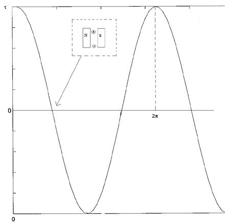
Where α is the angle between the plane of the armature turn and the initial position of the armature, which is here along the direction of magnetic field. The presence of the term cosα in the torque equation shows that although force the same at all positions but torque is not same at all the positions.

Fig (4): Relationship between torque and alpha (α) in DC motor.
DC motor | DC motor Assignment Help | DC motor homework help | Electrical engineering homework help | Electrical engineering Assignment Help| Electrical engineering project help| help with Electrical Engineering Courses.


