Counter Circuits Assignment Help
Objectives:

![]() to build and analyse the operation of an asynchronous counter
to build and analyse the operation of an asynchronous counter
![]() to modify the counter so that it will both count up and count down
to modify the counter so that it will both count up and count down
![]() to design and simulate a three digit decade counter.
to design and simulate a three digit decade counter.
Experimental Work

![]() Asynchronous Counters
Asynchronous Counters
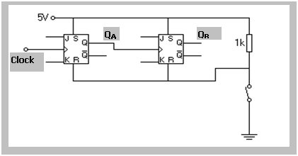
1. Construct the following circuit, with J = K = ‘1’ for both flip-flops.
2. Connect the Q outputs to LEDs and the clock input to the one-shot signal generator on the Logic Tutor.
3. Clear the counter and apply successive clock input pulses and record the Q outputs in Table 2(a).
Counter Circuits Assignment Help Through Online Tutoring and Guided Sessions from AssignmentHelp.Net
| Table 2(a) | Table 2(b) | |||
| Pulse | QA | QB | QA | QB |
| Clear | ||||
| 1 | ||||
| 2 | ||||
| 3 | ||||
| 4 | ||||
| 5 |
4. Now substitute the one-shot clock signal for the low frequency clock on the Logic Tutor and sketch the Clock, QA and QB output waveforms above each other on the same time axis.
5. Transfer the clock connection from the Q to QBAR output and repeat the above, enter your results in Table 2(b) and sketch the waveforms as before.
6. What is the difference between the two circuits?

![]() Up / Down Selector
Up / Down Selector
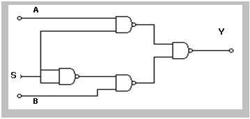
1. Construct the two input multiplexer circuit shown below.
2. Construct a truth table to prove that when S = ‘1’, Y follows A, when S = ‘0’, Y follows B
3. Connect the multiplexer circuit in between the two flip-flops such that Q is connected to A, QBAR to B and Y to the clock input of the second flip-flop.
Confirm that your counter counts up or down, depending on whether S is ‘1’ or ‘0’
Simulation Work
Design and simulate a three digit BCD counter, i.e. a counter that will count to 999 and then reset to 000. The output should be displayed on three seven segment displays.
Print out the circuit diagram and briefly describe the operation of your circuit
Assignment Help | Physics Assignment Help | Physics Homework Help | Online Tutoring | Sample Homework


