Building A Wien Bridge Oscillator Assignment Help
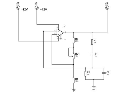
You are required to build and test the circuit given in figure 21.


Figure 21
This is similar to the circuit that you simulated earlier except that R3 and R4 have new values. R4 is 100k and R3 is 200k. R3 is now in series with a pot of 10k so that you can increase the feedback gain.
Building A Wien Bridge Oscillator Assignment Help Through Online Tutoring and Guided Sessions from AssignmentHelp.Net
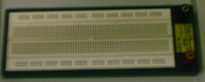
You will build the circuit on a plug in breadboard similar to that in figure 22.

Figure 22
Plug the 741 IC across the gap in the middle of the board. You can gain access to each pin from the internal tracks connected to the IC.
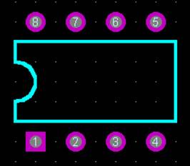
The pin connections for the Op Amp (741) is given in figure 21. Note that the IC pin out is shown in figure 23.

Figure 23
Measure the output amplitude and frequency from the Op Amp for various settings of the feedback gain.
Conclusions
Your laboratory report should describe each of the simulations in detail and include relevant screen shots. Discuss all aspects of the construction of your circuits and provide waveforms at positions that demonstrate their operation. Always comment on your results.
Building A Wien Bridge Oscillator | Online Tutoring | Sample Homework


