15FMCE211 Engineering Fluids and Applications
|
School/ Department Name |
School of Engineering / Mechanical Engineering |
|
Program Code and Title: |
EDMF15 - Diploma of Mechanical Engineering |
|
Assignment Code and Title: |
15FMCE211 – Engineering Fluids and Applications |
|
Assessment Number and Title: |
Experiment no. 1 - Title |
|
Assessment Type: |
Lab Report |
|
Section (s): |
P3M1 |
|
Assessment General Instructions: |
e.g. All questions must be answered correctly in order to meet assessment requirements. Please use black or blue pen, not pencil e.g If you require any assistance during the assessment please raise your hand and the supervisor will attend to you. e.g Talking, cheating, using mobile phones are not allowed during the assessment. |
I. OBJECTIVES
(1 Mark)
The objectives of this Bernoulli’s Theorem experiment are;
- To investigate the validity of the Bernoulli equation when applied to the steady flow of water in a tapered duct.
- To measure flow rates, static and total pressure heads in a rigid convergent or divergent tube of known geometry(VENTURI METER) for a range of steady flow rates.
The relation among the pressure, velocity and elevation in a moving fluid (liquid or gas), the compressibility and viscosity (internal friction) of which are negligible and the flow of which is steady or laminar is indicated in Bernoulli’s theorem.
II. INTRODUCTION AND THEORY
(2 Marks)
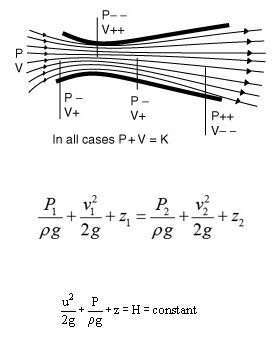
Bernoulli's Principle is a physical principle formulated that states that "as the speed of a moving fluid (liquid or gas) increases, the pressure within the fluid decreases”. Bernoulli's principle is named after the Swiss scientist Daniel Bernoulli who published his principle in his book Hydrodynamica in 1738.
Bernoulli's law states that if a non-viscous fluid is flowing along a pipe of varying cross section, then the pressure is lower at constrictions where the velocity is higher, and the pressure is higher where the pipe opens out and the fluid stagnate. Many people find this situation paradoxical when they first encounter it (higher velocity, lower pressure).
In a steady streamline flow of an ideal liquid, the sum of all energies present remains constant, provided no work isdone by the airflow or on it. In other words, in a horizontal flow the sum of kinetic energy and pressure energy isconstant or P + 1/2 ρV2 = K where P is the static pressure, is the density, V is the air speed, and K is a constant. From this law, it follows that where there is a velocity increase in a fluid flow, there must be a corresponding pressuredecrease.
III. APPARATUS
(1 Mark)
Bernoulli’s Theorem Demonstration Unit (Fig.1)
Tap water
- Manometer Tubes
- Test Section
- Water Inlet
- Unions
- Air Bleed Screw
- Flow Control Valve
- Gland Nut
- Hypodermic Probe
- Adjustable Feet
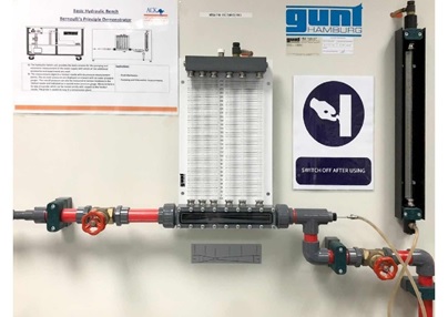
Bernoulli’s Demonstration Unit. Fig. 1
IV. METHODOLOGY AND PROCEDURE
(1 Mark)
1. General Start-up Procedures
The Bernoulli’s Theorem Demonstration (Model: FM 24) is supplied ready for use and only requires connection to the Hydraulic Bench (Model: FM 110) as follows:
- Ensure that the clear acrylic test section is installed with the converging section upstream. Also check that the unions are tighten (hand tight only). If necessary to dismantle the test section then the total pressure probe must be withdrawn fully (but not pulled out of its guide in the downstream coupling) before releasing the couplings.
- Locate the apparatus on the flat top of the bench.
- Attach a spirit level to baseboard and level the unit on top of the bench by adjusting the feet.
- Fill water into the volumetric tank of the hydraulic bench until approximately 90% full.
- Connect the flexible inlet tube using the quick release coupling in the bed of the channel.
- Connect a flexible hose to the outlet and make sure that it is directed into the channel.
- Partially open the outlet flow control valve at the Bernoulli’s Theorem Demonstration unit.
- Fully close the bench flow control valve, V1 then switch on the pump.
- Gradually open V1 and allow the piping to fill with water until all air has been expelled from the system.
- Also check for “Trapped Bubbles” in the glass tube or plastic transfer tube. You would need to remove them from the system for better accuracy.
Note:
To remove air bubbles, you will have to bleed the air out as follow:
- Get a pen or screw driver to press the air bleed valve at the top right side of manometer board.
- Press air bleed valve lightly to allow fluid and trapped air to escape out. (Take care or you will wet yourself or the premise).
Allow sufficient time for bleeding until all bubbles escape.
- At this point, you will see water flowing into the venturi and discharge into the collection tank of hydraulic bench.
- Proceed to increase the water flowrate. When the flow in the pipe is steady and there is no trapped bubble, start to close the discharge valve to reduce the flow to the maximum measurable flow rate.
- You will see that water level in the manometer tubes will begin to display different level of water heights. If the water level in the manometer board is too low where it is out of visible point, open V1 to increase the static pressure. If the water level is too high, open the outlet control valve to lower the static pressure.
Note: The water level can be adjusted facilitate by the air bleed valve.
- Adjust V1 and outlet control valve to obtain a flow through the test section and observe that the static pressure profile along the converging and diverging sections is indicated on its respective manometers. The total head pressure along the venture tube can be measured by traversing the hypodermic tube.
Note:
The manometer tube connected to the tapping adjacent to the outlet flow control valve is used as a datum when setting up equivalent conditions for flow through test section.
- The actual flow of water can be measured using the volumetric tank with a stop watch.
2. Experiment
- Perform the General Start-up Procedures in Section A.
- Check that all manometer tubings are properly connected to the corresponding pressure taps and are air-bubble free.
- Adjust the discharge valve to a high measurable flow rate.
- After the level stabilizes, measure the water flow rate using volumetric method.
3. General Shut-down Procedures
- Close water supply valve and venturi discharge valve.
- Turn off the water supply pump.
- Drain off water from the unit when not in use.
V. DATA AND CALCULATIONS
(5 Marks)
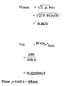
Hdyn = Htot – Hstat
= 180 – 180
= 0m
|
H1 mm ws |
H2 mm ws |
h3 mm ws |
h4 mm ws |
h5 mm ws |
h6 mm ws |
t 10l/sec |
q l/sec | |
|
hstat |
180 |
160 |
50 |
110 |
120 |
130 |
68 |
0.147 |
|
htot |
180 |
180 |
180 |
180 |
180 |
180 |
1.47*10 | |
|
hdyn |
0 |
20 |
130 |
70 |
60 |
50 |
|
h1 mm ws |
h2 mm ws |
h3 mm ws |
h4 mm ws |
h5 mm ws |
h6 mm ws | |
|
vmea. |
0 |
0.626 |
1.597 |
1.172 |
1.085 |
0.99 |
|
vcal. |
0.434 |
0.630 |
1.738 |
0.864 |
0.576 |
0.441 |
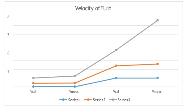
VI. RESULTS AND GRAPHS
(5 Marks)
VII. SAMPLE OF CALCULATIONS
(1 Mark)
Difference in Static and Total Pressure
Since the outside holes are perpendicular to the direction of flow, these tubes are pressurized by the local random component of the air velocity. The pressure in these tubes is the static pressure (ps) discussed in Bernoulli's equation. The center tube, however, is pointed in the direction of travel and is pressurized by both the random and the ordered air velocity. The pressure in this tube is the total pressure (pt) discussed in Bernoulli's equation. The pressure transducer measures the difference in total and static pressure which is the dynamic pressure q. measurement = q = pt – ps
Solve for Velocity
With the difference in pressures measured and knowing the local value of air density from pressure and temperature measurements, we can use Bernoulli's equation to give us the velocity. On the graphic, the Greek symbol rho is used for the dair density. In this text, we will use the letter r. Bernoulli's equation states that the static pressure plus one half the density times the velocity V squared is equal to the total pressure.
ps + .5 * r * V ^2 = pt
Solving for V:
V ^2 = 2 * &lbrace pt-ps &rbrace / r
V = sqrt [2 * &lbrace pt-ps &rbrace / r ]
where sqrt denotes the square root function
VIII. DISCUSSION
(5 Marks)
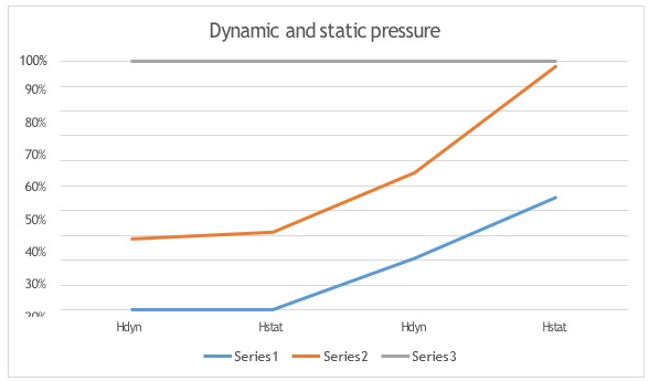
The goal of the experiment is to find out legitimacy of the Bernoulli’s mathematical statement when connected to the relentless flow of water in a decreased pipe. Bernoulli's Principle is essentially a work energy conservation principle which states that for an ideal fluid or for situations where effects of viscosity are neglected, with no work being performed on the fluid, total energy remains constant. This principle is a simplification of Bernoulli's equation, which states that the sum of all forms of energy in a fluid flowing along an enclosed path (a streamline) is the same at any two points in that path. The total head for convergent flow is decreased from h1 to h6 while the total head value for divergent flow is the lowest at h1 and the highest at h6. However it is to be noted that there might have been some human and apparatus related errors unintentionally done in the experiment process which might have given us some deviated results from the actual results. However, the results can be improved if some precautions are taken during the experiment for example the eyes level must be placed parallel to the scale when manometer readings are taken. Besides that, the valve is also needed to be controlled slowly to stabilize the water level in the manometer. The human reaction error while noting the time using a stop watch can be avoided by using light gates to give out highly accurate results for the time measured. Bernoulli’s theorem has several applications in everyday lives. In certain problems in fluid flows when given the velocities at two points of the streamline and pressure at one point, the unknown is the pressure of the fluid at the other point. In such cases (if they satisfy the required condition for Bernoulli's Equation) Bernoulli's Equation can be used to find the unknown pressure. One such example is the flow through a converging nozzle.
- Common sources of random errors are problems estimating a quantity that lies between the graduations (the lines) on an instrument as well as the inability to read an instrument due to reading fluctuates during a measurement.
- If valid, the percentage error should be calculated to determine the error and to measure the accuracy of a measurement by the following equation (the difference between a measured or experimental value E and a true or accepted value A).
IX. CONCLUSIONS AND RECOMMENDATIONS
(2 Marks)
From the experiment conducted, there are different cross-sections for each tube H1, H2, H3, H4, H5, and H6. These differences resulted in varieties of value obtained for stagnation head (H) and pressure head (hi). By using Bernoulli equation to calculate the velocity, it can be said that the velocity of fluid increase as the fluid is flowing from a wider to narrower tube and the velocity decrease in the opposite direction. This also indicates that the pressure of fluid decreases as the velocity increases. Therefore, the Bernoulli’s principle is proven.
The Bernoulli equation forms the basis for solving a wide variety of fluid flow problems such as jets issuing from an orifice, flows associated with pumps and also turbines. Bernoulli’s equation is also useful in demonstration of aerodynamic properties such as drag and lift.
From the data and results calculated, we can conclude that the Bernoulli equation is valid for flow as it obeys the equation and the objectives are successfully achieved.
There are some practical limitations to the use of a Device:
- If the velocity is low, the difference in pressures is very small and hard to accurately measure with the transducer. Errors in the instrument could be greater than the measurement! So pitot-static tubes don't work very well for very low velocities.
- If the velocity is very high (supersonic), we've violated the assumptions of Bernoulli's equation and the measurement is wrong again. At the front of the tube, a shock wave appears that will change the total pressure. There are corrections for the shock wave that can be applied to allow us to use pitot-static tubes for high speed aircraft.
- If the tubes become clogged or pinched, the resulting pressures at the transducer are not the total and static pressures of the external flow. The transducer output is then used to calculate a velocity that is not the actual velocity of the flow. Several years ago, there were reports of icing problems occuring on airliner pitot-static probes. Output from the probes was used as part of the auto-pilot and flight control system. The solution to the icing problem was to install heaters on the probes to insure that the probe was not clogged by ice build-up.
X. REFERENCES
(1 Mark)
- Douglas, J.F.Gasiorek, J.M. and Swaffield, J.A.(1999) Fluid Mechanics, 3rdedition. Longmans Singapore Publisher, Pg. 99-101
- Giles, R.V., Evett, J.B. and Cheng Liu, Schaumm’s (2010)Outline Series Theory and Problemsof Fluid Mechanics and Hydraulic, McGraw Hill Intl. Pg.559-620
XI. DATA APPENDIX/ DATA WORKSHEET
(1 Mark)
|
OBJECTIVE |
5 |
|
INTRODUCTION AND THEORY |
6 |
|
APPARATUS |
7 |
|
METHODOLOGY AND PROCEDURE |
8-9 |
|
DATA AND CALCULATION |
9-11 |
|
RESULTS AND GRAPH |
10-11 |
|
SAMPLE OF CALCULATION |
11-12 |
|
DISCUSSION |
12-13 |
|
CONCLUSION AND RECOMMENDATIOS |
14-15 |
|
REFERNCES |
16 |


